
Operating instructions

3-16
Installation
Tips
for
Minimizing Unwanted
Triggering
(continued)
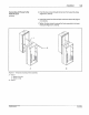
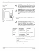
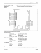
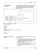
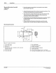
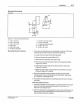
Mounting Dimensions
Figure 3.
11
- Sensor dimensions
1- 1.21 in.
(3
0.7 mm)
2-
0.95 in. (2
4.
1 mm)
3 -
30
ft
(9.
1 m)
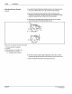
• Mount the sensor to metal that is connected to earth safety
ground (system ground).
• Adjust photosensor gain
to
the minimum required sensitivity. This
will reduce both electrical and optical problems.
•
The
photosensor cable shield should be grounded at both ends.
Th
is will reduce the effects
of
electrical noise produced by
contactors, motors, and arc-welders.
•
Th
rough-beam and retroreflective photosensors should be used in
the light operate mode. This also
will reduce the effects
of
electrical noise.
• Diffuse reflective photosensors should be used in the dark
operate mode. This
will reduce the effects
of
electrical noise.
'
.
'
13
7-2.1
in. (53.3 mm)
8 - Gasketed, acrylic cover
9 - 0.48 in. (12.2
mm)
4 - Mounting peg; 0.
25
in. diameter x 0.
10
in. (6.4 mm
diameter
x 2.5 mm)
10-
114
screw clearance (2 places)
11
- 1.
08
in. {27.4 mm)
5 -
0.75
in (19.1 mm)
6 - 1.5 in. (38. 1 mm)
PIN 108 389A
57
·28 1/93
12-
0.
71
in.
{18
mm) diameter; 18 x 1
mm
thread
13-
Mounting nut (supplie
d),
0.95 in.
(24
.1 mm) diameter
o
No
t
dson
Co
tPO
tallon 19ll3
All Rl
gncs
ReS"tved