
Operating instructions
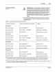

Mounting Dimensions
(
con
tinued)
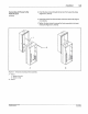
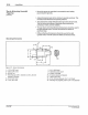
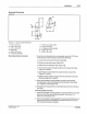
Figure 3.
12
- Sensor bracket dimensions
1-0
.
10
in. (2.5 mm)
2 -
0.
79
in. (20. 1 mm)
3-
1
.7
9 in. (45.5 mm)
4 -
90 degrees
5 -
0.80 in. (20.3 mm)
6 -
10
degrees (typically)
Mounting Nordson Sensors
Q
Na<CSon
Corporaijon 1993
AU R
ightS
Reserved
Installation 3-17
7-
0. 170 in. (4.3 mm); 2 slots
8 - 1.
25
in.
(31
.8 mm)
9-
15
degrees (either direction)
10-0
.120 in. (3.1 mm)
11
- 0.120
in.
(3.1 mm)
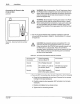
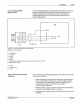
1.
If
you have not already done so, temporarily mount the PC40 front
assembly to the back enclosure
by
doing the following:
a. Loosen the
six
screws on the front assembly.
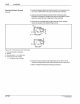
b. Remove the two top screws {Figure 3.5).
c. Rotate the front assembly
180" {Figure 3.6).
d. Push the
two
scr
ews through the top two front assembly holes
{Figure 3.7, view A).
e.
Insert the two screws into the two back enclosure stand-offs
(Figure 3.7, view A).
f.
lighten
the two screws to secure the front assembly
to
the back
e~closure
(Figure 3.7, view
B)
.
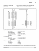
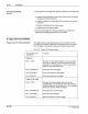
2. Check the intended mounting position to make sure that there
enough space to mount the sensor(s) and bracket(s).
See Figure
3.
11,
Figure 3.12 and Figure 3.13.
3. Proceed to the instructions for mounting the type
of
sensor that you
are using.
Mounting Diffuse Sensors
1.
Check
the
intended mounting position
to
ensure that there is enough
space to mount the sensor(s) and bracket(s) .
See Figure 3.
11
,
Figure 3.12, and Figure 3.13.
2. Check the intended mounting position
to
make sure that there are no
objects other than the substrate that
will pass between the sens
or
and substrate during line operation.
P
iN
108 389A
57-28 1
/9
3