
Operating instructions

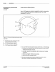

Nordson Photosensor Wiring
Connections
Installation
3-21
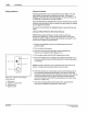
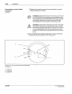
WARNING: Risk
of
electrocution.
The
AC
input power line to
the
PC40 provides voltage that can cause personal injury or
death. Before making any electrical connections, disconnect
and lock out power
to
the main circuit breaker for the input
power line (see Figure 3.8).
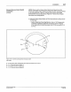
1.
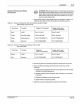
Connect the wires for each photosensor as indicated in Table 3.7 or
Table 3.8. See Figure 3.9
for
the location
of
terminal block P4.
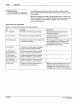
Table
3.
7 - Nordson Photosensor Wire Connections (except Through-
beam Emitter, PIN
131
473)
Wire Color Function Trigger
#1
Connection Trigger #2 (if used)
Terminal Connection
Red
+VDC P4-1 ("+12V"} P4-5
("
+ 12V")
Green Sourcing output None; clip lead. None; clip lead.
White Sinking output
P4-2 ("TRIGGER 1"} P4-6 ("TRIGGER 2")
Black Common P4-3
("GROUNDj
P4-7
("GROUNDj
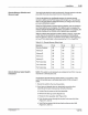
Table 3.
8-
Nordson Through-beam Emitter,
PIN
131
473
Wire Color Code
Wire
Color
Brown
Blue
e N
O<
dson
Co
rpor
a
~o
n
1993
AI Righ
ls
Re
s-d
Function
+VDC
Common
Trigger
#1
Terminal Connection
Trigger
#2 (if used)
Terminal Connection
P4-1
("+12V") P4-5
("
+ 12V")
P4-3
("GROUNDj
P4-7
("GROUNDj
2. Ground the other end
of
each photosensor shield near the sensor.
3.
If
you are NOT connecting remote devices
at
this time,
do
the
following:
a.
Grasp the front assembly with one hand. Remove the two screws
holding
it
to
the back enclosure.
b.
Carefully rotate the front assembly 180" and place it on the back
enclosure.
c. Replace and tighten the two loose screws.
d. Tighten the four remaining screws.
4. Align the sensors by following the instructions that follow.
PIN 108 389A
57-28 1/93