
Operating instructions


3·22
Installation
Aligning
Sensors
.....,...+----1
4----.;..·0
.....,.....>-!---
2
3 0
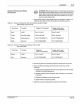
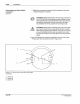
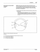
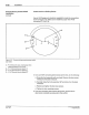
Figure 3.
14
-Al
ignment LED and gain
control locations
1
- Gain control
2-
Light/dark operate switch
3
- Cable opening
4
-Alignment
L£0
PIN
108
389A
57·28
1193
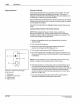
Alignment
Indicator
Nordson photosensors have an alignment indicator (LED).
The
LED
pulse (flash) rate increases as
alignment improves. The sensor is
adjusted so that the LED is off (not flashing) in the dark condition or is
on
(flashing) at a fast rate in the light condition.
The LED flash rate also indicates when sensor maintenance is needed.
Whenever the flash
rate is slow, the sensor's lenses should be cleaned
and the
alignment checked.
Proceed to the instructions for aligning the type
of
sensor that you are
using.
Aligning
Diffuse Reflective (Proximity) Sensors
NOTE: Before adjusting the gain control, make sure that any
background objects (e.g., moving machine parts which would pass
through the sensor's field
of
view during operation) are present in the
sensor's line of sight during adjustment.
1. Remove the gasketed acrylic cover located above the sensor
electrical cable.
2. Turn on power to the sensor.
3. Direct the infrared sensor light beam
at
the substrate and
observe the red alignment LED (Figure 3.14).
4.
Turn the gain control until the LED is flashing on and off.
5. Move the substrate and, if possible, any background objects out
of
the sensor's field
of
view. If the LED stays off, no further adjustment
is necessary.
NOTE: The gain control is a 15-turn pot which does not have a stop
position. The gain control ratchets
at
the end
of
its travel.
6.
If the LED remains on, turn the
ga
in control counterclockwise by
1..2
turn increments until the sensor comes on only when it "sees" the
substrate, but goes off when the substrate is removed.
If the LED still
remains on after you turn the gain control fully counterclockwise,
remount the
sensor further from the substrate (but no further away
than 15 in.
or
38.1 em).
7.
If you are connecting other devices
at
this time, proceed
to
the
appropriate installation procedure(s) in this section.
C>
Nor
dson
Corpo
rat
ion
1993
All Rights Reserved