
Operating instructions


Aligning
Sensors
(continued)
C'J
N
O<
ds
on
Corpornon
1993
AI Right$
Res..ved
Installation 3-23
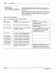
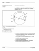
Aligning Opposed (Through Beam) Sensors
1. Remove the gasketed acrylic cover located above the sensor
electrical cable.
2.
Turn on power to the sensor.
3.
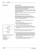
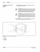
Direct the emitter at the receiver and observe the red alignment LED
on the receiver (Figure 3.14).
4. Turn the gain control to the
fully clockwise position. The LED should
be flashing on and
off
.
5. Adjust the position
of
the emitter and/or receiver to achieve the
maximum alignment LED flash rate.
6.
Move the substrate between the emitter and receiver.
If
the LED
stays off,
no
further adjustment is necessary.
7.
If the LED continues to flash on and off,
or
remains on, turn the
ga
in
control counterclockwise
by
1~
turn increments until the LED goes
out and stays off.
8.
If you are connecting other devices at this time, proceed to the
appropriate installation
procedt,Jre(s) in this section.
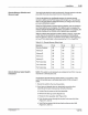
Aligning Retroreflectlve Sensors
1 . Remove the gasketed acrylic cover located above the sensor
electrical cable.
2. Turn on power to the sensor.
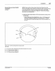
3. Direct the infrared light beam on the emitter/receiver at the reflector
and observe the red alignment LED (Figure 3.14).
4. Turn the gain control to the
fully clockwise position. The LED should
be flashing on and off.
5. Move the substrate between the emitter/receiver and reflector.
If the
LED stays off, no further adjustment is necessary.
6.
If the LED continues to flash on and off, or remains on, turn the gain
control counterclockwise by
,
~
turn increments until the LED goes
out and stays off.
If
the LED still remains on after you tum the gain
control
fully counterclockwise, take steps to reduce the reflectivity
of
the substrate.
7.
If
you are connecting other devices
at
this time, proceed to the
appropriate installation procedure(s) in this section.
PIN 108 389A
57
·28 1/93