
Operating instructions


3-24 Installation
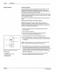
9. PC40 Remote
Communications Installation
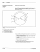
The following information is provided
if
you will be using a remote
device
to
se
lect active memory and/or lock out input through the PC40
user interface.
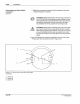
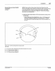
Remote connections are made to
PC40 terminal block
P1
(Figure 3.9).
Signals connected to
P1
are optically isolated from the remote system.
The opto-isolators can be turned
on
by either current sourcing
or
current sinking devices.
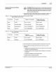
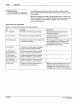
Remote Pin Characterization
Table
3
~
9
- Remote Communication Pin Characterization
Pin
P1-1
("Shield")
P1-2 ("Ground")
P1
-3 ("Common")
Pl-4
("lock")
P1-5 ("Remote
Memory Select 3")
P1
-6 ("Remote
Memory Select 2")
P1-7 ("Remote
Memory Select 1 ")
P1-8
{"+1
2V")
PIN
10838
9A
57
-28
11!13
Function
Provided for field wiring convenience.·
Provided for field wiring convenience.
Provides
for
one half
of
the connection for
all of the opto
-i
solators.
Provides
for
a remote signal to disallow
access
to
the PC40 Program Mode.
Provides con
ne
ction to allow a remote
devi
ce
to
change the active memory.
Provides connection to allow a remote
device to change the active memory.
Provides connection to allow a remote
device to change the active memory.
Provides 12 VDC input power for any
remote
dev
ice that requires it.
Comments
Connected
to
the remote device
1/0
printed circuit board.
Connected
to
the remote device
1/0
printed circuit board.
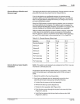
For sourcing
(PNP) devices, P1-3 should
be connected to
P1-2 ("Ground"). For
sinking
(NPN) devices, P1-3 should be
connected
to
P1-8 ("+12V").
Maximum current available from pin
P1
-8
is 500 mA.This is the maximum current
available for
all connections to pin
P1
-8
including loads on other PC40 connectors.
C N
ord
son Corporation 1993
All
R
1g
~
ts
Reserved