
Operating instructions


3-26
Installation
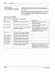
Remote Memory Select Switch
Installation
(continued)
2
3
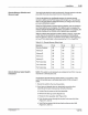
f.
lighten
the two screws
to
secure the front assembly to the back
enclosure (Figure
3.7, View B).
WARNING: Risk
of
electrocution. The
AC
input power line to
the
PC40 240 VAC power supply) provides voltage that can
cause personal injury
or
death. Before making any electrical
connections, disconnect and lock out power to the main
circuit breaker for the input power line (see Figure 3.8).
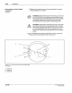
WARNING: Shock hazard. Touching bare wires in the PC40
can result in shock that can cause personal injury or death.
When making electrical connections, make sure to strip only
as much insulation from the wires as needed.
Also, make
sure that the insulation fits snugly against the
PC40 terminal
blocks.
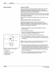
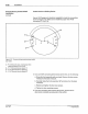
3. Use 18-22 gauge wire (customer supplied) to make the
sw
itch and
PC40 jumper wire connections shown in Figure 3.15.
A
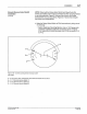
Figure 3. 15 -
Memory
se
l
ec
t switch {rear v
ie
w)
jumper
connections
1 -
Jumper
111
2 -
Jumper
112
3 -
Jumper
113
P
IN
10838
~
57·28 1
/9
3
Cl
NOfdson
CO
r
poroo
oo
n 1993
All At
gh
ts Reserved