
Operating instructions


Remote Memory Select Switch
Installation
(contin
ued)
c
Installation 3-27
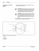
NOTE:
When both the Rotary Select Switch and Keyed Lock Out
Switch
are installed, both must be connected as either sourcing devices
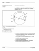
or as sinking devices. Figure 3.16 shows the wiring for the Rotary
Select Switch
as
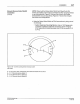
a sourcing device. Figure 3.17 shows the wir
in
g for
the switch
as
a sinking device.
4. Make
the
Rotary Select Switch
to
PC40 connections by
do
ing
one
of
the followi
ng
:
• Switch Used as a Sourcing Device -
Use
an 18·22 gauge wire
(customer supplied)
to
make the connections shown
in
Figure
3.
16
. Make
su
re
to
Install the jumper from PC40 connecti
on
P1·2
to P1·3.
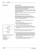
A
Figure 3. 16 • Current sourcing remote memory switch
(rear view)
A-
P1-8 ("+12'V); also, install
jumper
from PC40 connection P1
-2
to
Pt
-3
B - P1-7 ("Remote Memory Select
1")
C-
Pt-6
("Remote Memory Select 2")
D -
Pt
-5
("
Remote Memory Select 3")
0 Natdson Corporabon 1993
AI Rights Resetved
PIN 108 389A
S7-28 1/93