
Operating instructions


3-28 Installation
Remote Memory Select Switch
Installation
(continued)
c
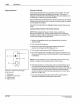
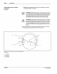
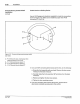
Switch Used as a Sinking Device
Use an 18-22 gauge wire (customer supplied)
to
make the connections
shown in Figure 3.
17
. Make sure
to
install the jumper from PC40
connection
P1
-3 to P1-8.
A
Figure 3. 17 - Current sinking remote memory switch
(rear view)
A - P1-2
(Groundj;
also, install jumper from
PC40 connection P1-3 to P1-8
8-
P1
-7 ("Remote Memory Select 1?
C-
P1
-6 ("Remote Memory Select
2j
D
.-
P1-5 (Remote Memory Select
3"r
PIN
108 389A
57·28
1193
5. If you are
NOT
connecting other devices
at
this time,
do
the following:
a. Grasp the front assembly with one hand. Remove the two screws
holding it to the back
enclosure.
b. Carefully rotate the front assembly 180" and place
it
on the back
enclosure.
c. Replace and tighten the two loose screws.
d. Tighten the four remaining screws.
6.
If you are connecting other devices at this time, proceed to the
appropriate installation procedure(s) in this section.
C Nordson Corporation 1993
All
R1ghts Reserved