
Operating instructions


Keyed
Lock
Out
Switch
Installation
Cl
N
O<dso
n
Co
r
poration
1993
M Rights Reserved
Installation 3-29
NOTE: This
sw
itch is not intended to be installed in the PC40.
It
can be
mounted on a remote panel,
etc
.
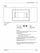
The
Nordson Keyed Lock
Out
Switch
is
an A-lock type, 4-tumbler
switch that prevents any input
via
the PC40 user interface.
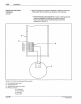
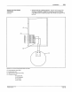
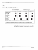
NOTE: When both the Keyed Lock
Out
Switch
and
Rotary Select
Switch
are installed, both
must
be
connected as either sourcing devices
or
as
sinking devices. Figure 3.18 shows the wiring for the Keyed Lock
Out Switch
as
a sourcing device. Figure 3.19 shows the wiring for the
sw
itch as a sinking device.
1.
Secure the
sw
itch
to
the mounting surface.
2.
If you have
not
already done so, temporarily mount the front
assembly to the back enclosure by doing the following:
a.
Loosen the six screws on the front assembly.
b.
Remove the two top screws (Figure 3.5).
c. Rotate the front assembly
1eo•
(Figure 3.6).
d. Push the two screws through the top two front assembly holes
(Figure 3.7, view A).
e.
Insert the two screws into the two back enclosure stand-offs
(Figure 3.7, view A).
f. Tighten the two screws
to
secure the front assembly to the back
enclosure (Figure 3.7, vi
ew
B)
.
WARNING: Risk
of
electrocution. The AC input power line to
the
PC40 provides voltage that can cause
pe
rsonal injury
or
death. Before making any electrical connections, disconnect
and lock out power to the main circuit breaker for the input
power
line (Figure 3.8) .
WARNING: Shock hazard. Touching bare wires in the PC40
can result in shock that can cause personal injury
or
death.
When making electrical connections, make sure
to
strip only
as much insulation from the wires as needed. Also, make
sure that the insulation fits snugly against the
PC40 terminal
blocks.
PIN 1
08
389
A
57-
28
1
/93