
Operating instructions


3-30 Installation
Keyed
Lock
Out
Switch
Installation
(ccntinued)
P1
A
P1-1
P1-2
P1-3
P1-4
P1
-5
P1
-6
P1·7
P1-8
0
0
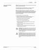
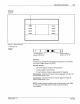
3. Use 18-22 gauge wire (customer supplied) to make the
sw
itch and
PC40 jumper wire connections by doing one of the following
•
Switch
Used
as
a
Sourcing
Device
- Use
an
18-22 gauge wire
{customer supplied)
to
make the connections shown in
Figure 3
.1
8. Make sure
to
install the jumper from PC40
connection P1-2 to P1-3.
~---------+4------8
0
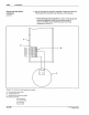
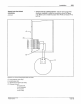
Figure 3.18 - Current sourcing keyed lock
out
sw
itch
A - Front assembly (rear view)
B - Install jumper wire
C - Keyed lock
out
switch (rear view)
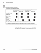
P1
{Remote
Control"):
PIN
108389A
57
·28
1153
Pt
-2 ("Ground)
P
t
·3
("Common•)
P1-4
("Lock?
Pt-8
("+12Vj
Cl
Nordsoo Corporallon 1993
Al
l
Roghts
Reserv-.1