
Operating instructions


Keyed
Lock
Out
Switch
Installation
(continued)
A
B
P1-1
P1-2
P1-3
P1-4
P1-5
P1·6
P1-7
P1·8
0
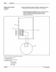
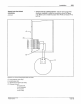
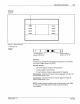
Figure 3.
19-
Current sinking keyed lock out switch
A - Front assembly (rear view)
B
-Install
jumper wire
C - Keyed lock out switch (rear view)
Pt
("Remote Control"):
P
1-2
("Ground}
P1
-3 ("Common")
P1-4
("Lock}
P1·8 ("+12V")
0 Not
<!Son
Corpora
don
1993
AI Roghls Res.....ed
Installation 3-31
•
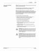
Switch
Used
as
a
Sinking
Device - Use an 18-22 gauge wire
(customer supplied) to make the connections shown in Figure
3.19. Make sure to
install the jumper from PC40 connection P1-3
to
P1
-8.
0
PIN 108
389A
57·28
1/93