
Operating instructions


3-32 Installation
Keyed
Lock
Out
Switch
Installation
(continued)
PIN 104 389A
57
-28 1/93
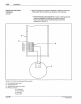
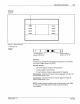
4.
If
you are NOT connecting other devices at this time,
do
the following:
a.
Grasp the front assembly with one hand. Remove the two screws
holding
it
to the back enclosure.
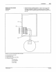
b.
Carefully rotate the front assembly
1ao•
and place it on the back
enclosure.
c. Replace and tighten the two loose screws.
d.
Tighten the four remaining screws.
5.
If you are connecting other devices at this time, proceed to the
appropriate procedure(s) in this section.
C Nordson
Cor
p
or
al
oon
1993
All R
ogh1s
R
es
e"'ed