
Operating instructions


Channel
(continued)
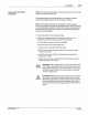
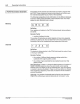
Figure 4. 1 - Be
ad
sequenc
es
1 - Bead (gun on)
Trigger
Cl NO<d$on
Corporation
1
993
AI
R
tg~l$
Rese<Ve
cl
1
---
-
-
-
Operating Instructions 4-3
-
-
-
-
1 2
~
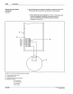
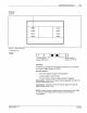
Symbol depicts J
sensor "
off'
to won"
~
xl
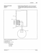
~
Symbol depicts
sensor
"on" to "off'
Definition:
A device (e.g
.,
photosensor) that senses the approach
of
a substrate
and sends a trigger signal to the
PC40.
Decision Factors:
• one
or
two triggers needed for
the
application
• assign a trigger
to
each channel
•
for
each channel, choose an edge symbol for triggering
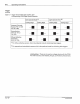
Dark Operate - Whenever the sensor receiver does
not
"see" light, the
sensor output device is
"on."
light
Operate - Whenever the sensor receiver does usee" light, the
sensor output device is
"on."
--
NOTE: Nordson sensors are factory-set for light operate mode. Table
4.1
tells you which edge symbol
to
select for each operati
ng
circumstance.
PIN 108
38
9A
57
·28 1
19
3