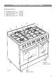
Twin cavity gas cookers RC 9320 ..
Dear Customer Thank you for choosing one of our appliances, carefully designed and built by our specialist staff and thoroughly tested to satisfy your cooking requirements. We suggest that you read this Instruction Booklet so that you will understand fully how to operate your appliance. Please keep the booklet handy. You may wish to refer to it at a later date.
Contents Model RC 9320 .. Page Number Introduction . . . . . . . . . . . . . . . . . . . . . . . . . . . . . . . . . . . . . . . . . . . . . . 4 Assembling the backguard . . . . . . . . . . . . . . . . . . . . . . . . . . . . . . . . . . . . 4 Features and technical data . . . . . . . . . . . . . . . . . . . . . . . . . . . . . . . . . . . 5 Control panel . . . . . . . . . . . . . . . . . . . . . . . . . . . . . . . . . . . . . . . . . . . . . 6 Minute counter . . . . . . . . . . . . . . . . . . . . . . . .
Introduction Congratulations on your purchase of this CDA cooker which has been carefully designed and produced to give you many years of satisfactory use. Before using this appliance it is essential that the following instructions are carefully read and fully understood. We would emphasise that the installation section must be fully complied with for your safety to ensure that you obtain the maximum benefits from your appliance.
Features and technical data Gas burners 1. 2. 3. 4. Auxiliary burner (A) Semi-rapid burner (SR) Rapid burner (R) Triple-ring burner (TR) 1,00 kW 1,75kW 3,00 kW 3,50 kW 1 3 2 1 4 2 Right Gas oven Fig.
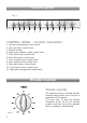
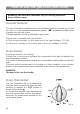
Control panel Fig. 3 1 2 3 4 5 6 7 8 9 10 11 CONTROL PANEL - Controls description 1. Left gas oven/gas grill control knob 2. Left oven light control knob 3. Minute counter 4. Right oven rotisserie / light control knob 5. Front left burner control knob 6. Rear left burner control knob 7. Front central burner control knob 8. Rear central burner control knob 9. Rear right burner control knob 10. Front right burner control knob 11.
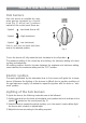
How to use the hob burners Hob burners Each hob burner is controlled by a separate gas tap operated by a control knob (fig. 5) which has 3 positions marked on the control panel, these are: – Symbol : tap closed (burner off) – Symbol : High (maximum) – Symbol : Low (minimum) Push in and turn the knob anti-clockwise to the selected position. Fig. 5 To turn the burner off, fully rotate the knob clockwise to the off position: .
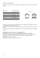
Choice of burner The burner must be chosen according to the diameter of the pans and energy required. Burners Pan diameter Auxiliary Semi-rapid Rapid Triple-ring Wok 12 ÷ 14 cm 16 ÷ 24 cm 24 ÷ 26 cm 26 ÷ 28 cm max 36 cm Fig. 6 do not use pans with concave or convex bases Saucepans with handles that are excessively heavy in relation to the weight of the pan are less safe as they are more likely to tip. Pans which are positioned centrally on burners are more stable than those which are offset.
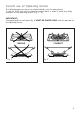
Correct use of triple-ring burner The flat-bottomed pans are to be placed directly onto the pan-support. To use the WOK you need to place the proper stand in order to avoid any faulty operation of the triple-ring burner (Fig. 7 - 8). IMPORTANT: The special grille for wok pans (fig. 8) MUST BE PLACED ONLY over the pan-rest for the triple-ring burner. CORRECT WRONG Fig. 7 Fig.
How to use the gas oven (left oven) Attention: the oven door becomes very hot during operation. Keep children away. General features The oven is furnished completely clean; it is advisable, however, upon first use, to turn the oven on to the maximum temperature (position ) to eliminate possible traces of grease from the oven burner. The same operation should be followed for grill burner.
Lighting the oven gas burner The thermostat allows the automatic control of the temperature. The gas delivery to the oven burner is controlled by a two way thermostatic tap (oven and grill burners) with flame-failure device. To light the oven burner operate as follow: 1) Open the oven door WARNING: Risk of explosion! The oven door must be open during this operation. 2) Lightly press and turn the thermostat knob anti-clockwise to max position “ ” (fig. 11).
How to use the gas grill (left oven) Lighting the grill gas burner Do not grill with oven door closed. Always fit the heat shield supplied with the cooker under the front panel before commencing operations (Fig. 14). WARNING. The heat shield and the oven door reaches a very high temperature whilst in use. Keep children away and allow to cool before removing. The grill burner generates the infra-red rays for grilling. To light the grill burner operate as follow: 1) Open the oven door.
Use of the grill Very important: the grill must always be used with the oven door slightly open and with shield "A” mounted (Fig. 14). Mount shield “A” which serves to protect the control panel from the heat. Turn on the grill, as explained in the preceding paragraphs and let the oven preheat for about 5 minutes with the door ajar. Introduce the food to be cooked, positioning the rack as close to the grill as possible. The dripping pan should be placed under the rack to catch the cooking juices and fats.
How to use the gas oven (right oven) Attention: the oven door becomes very hot during operation. Keep children away. General features The oven is furnished completely clean; it is advisable, however, upon first use, to turn the oven on to the maximum temperature (position ) to eliminate possible traces of grease from the oven burner. The same operation should be followed for grill burner.
Lighting the oven gas burner The thermostat allows the automatic control of the temperature. The gas delivery to the oven burner is controlled by a two way thermostatic tap (oven and grill burners) with flame-failure device. To light the oven burner operate as follow: 1) Open the oven door WARNING: Risk of explosion! The oven door must be open during this operation. 2) Lightly press and turn the thermostat knob anti-clockwise to max position “ ” (fig. 18).
How to use the gas grill (right oven) Lighting the grill gas burner Do not grill with oven door closed. Always fit the heat shield supplied with the cooker under the front panel before commencing operations (Fig. 21). WARNING. The heat shield and the oven door reaches a very high temperature whilst in use. Keep children away and allow to cool before removing. The grill burner generates the infra-red rays for grilling. To light the grill burner operate as follow: 1) Open the oven door.
Use of the grill H O T Z O N E Very important: the grill must always be used with the oven door slightly open and with shield "A” mounted (Fig. 21). Mount shield “A” which serves to protect the control panel from the heat. Turn on the grill, as explained in the preceding paragraphs and let the oven preheat for about 5 minutes with the door ajar. Introduce the food to be cooked, positioning the rack as close to the grill as possible.
Rotisserie (right oven) This is used for spit roasting under the grill and comprises: – an electric motor fitted to the rear of the oven – a stainless steel skewer provided with slide-out heatless handgrip and two sets of adjustable forks – a skewer support to be fitted in the middle runner. The rotisserie motor is operated by a switch knob (Fig. 23). Fig. 23 Use of the rotisserie Very important: the rotisserie must always be used with the oven door ajar and with shield “A” mounted (Fig. 21).
Oven cooking temperatures MARK APPROX. TEMP. HEAT OF OVEN TYPE OF DISH TO COOK 130 130°C Very cool oven Meringue cakes, slow cooking items • 140°C Cool or slow oven Milk puddings, very rich fruit cakes, i.e., Christmas 155 155°C Cool or slow oven Stews, casseroles, braising, rich fruit cakes, i.e., Dundee • 165°C Warm oven Biscuits, rich plain cakes i.e., Madeira. Low temp.
Do’s and do not’s Do’s and do not’s • Do not grill with oven door closed. Always fit the heat shield supplied with the cooker under the front panel before commencing operations. • Do read the user instructions carefully before using the cooker for first time. • Do allow the oven to heat for one and a half hours, before using for the first time, in order to expel any smell from the new oven insulation, without the introduction of food. • Do clean your oven regularly. • Do remove spills as soon as they occur.
For your safety The product should only be used for its intended purpose which is for the cooking of domestic foodstuffs. Under no circumstances should any external covers be removed for servicing or maintenance except by suitably qualified personnel. Attention The appliance gets very hot, mainly around the cooking areas. It is very important that children are not left alone in the kitchen when you are cooking. Oven door guard The glass on the oven door reaches high temperatures during operation.
Care and maintenance Important: As a safety measure, before you start cleaning the cooker be sure to disconnect it from the mains supply. Do not use a steam cleaner because the moisture can get into the appliance thus make it unsafe. The use of suitable protective clothing/gloves is recommended when handling or cleaning of this appliance. WARNING When correctly installed, your product meets all safety requirements laid down for this type of product category.
Enamelled parts All the enamelled parts must be cleaned with a sponge and soapy water only or other non-abrasive products. Dry preferably with a microfibre or soft cloth. Stainless steel, aluminium, painted parts and silkscreen printed surfaces Clean using an appropriate product. Always dry thoroughly. Stainless steel surfaces: can be cleaned with an appropriate stainless steel cleaner. IMPORTANT: these parts must be cleaned very carefully to avoid scratching and abrasion.
Burners They can be removed and washed only with soapy water. Detergents can be used but must not be abrasive or corrosive. Do not use abrasive sponges or pads. Do not put in dishwasher. After each cleaning, make sure that the burner-caps, as well as the burners, have been well wiped off and CORRECTLY POSITIONED. It is essential to check that the burner flame distributor F and the cap C has been correctly positioned (see fig. 25) - failure to do so can cause serious problems.
Removal of the inner glass door panel – The inner glass door panel can easily be removed for cleaning by unscrewing the fixing screws (fig. 28). – When re-assembly ensure that the inner glass is correctly positioned and do not over tighten the screws. Do not use harsh abrasive cleaners or sharp metal scrapers to clean the oven door glass since they can scratch the surface, which may result in shattering of the glass. Fig.
Inside of oven The oven should always be cleaned after use when it has cooled down. The cavity should be cleaned using a mild detergent solution and warm water. Suitable proprietary chemical cleaners may be used after first consulting with the manufacturers recommendations and testing a small sample of the oven cavity. Abrasive cleaning agents or scouring pads/cloths should not be used on the cavity surface. Fig.
Removing the oven door Fig. 32a Please operate as follows: • Open the door completely. • The swivel retainers of the rh and lh hinges (fig. 32a) are hooked onto the metal bar above them (fig. 32b). • Lift the oven door slightly. The noch on the bottom of the hinge will disengage (fig. 32c). • Now pull the oven door forwards off the appliance. Release both hinge sections from the slots (fig. 32d). Fig.
FOR THE INSTALLER Location This cooker has class “2/1” overheating protection so that it can be installed next to a cabinet. The appliance may be installed in a kitchen, Kitchen/diner or a bed sitting room, but not in a room or space containing a bath or a shower. The appliance must not be installed in a bed-sitting room of less than 20 m3. The appliance is designed and approved for domestic use only and should not be installed in a commercial, semi commercial or communal environment.
The cooker must be installed by a qualified technician and in compliance with local safety standards. 450 mm 650 mm If the cooker is located on a pedestal it is necessary to provide safety measures to prevent falling out. 200 mm 500 mm ent air v Fig.
Fitting the adjustable feet The adjustable feet must be fitted to the base of the cooker before use. Rest the rear of the cooker an a piece of the polystyrene packaging exposing the base for the fitting of the feet. Fig. 34 Fig. 35 30 Fit the 4 legs by screwing them tight into the support base as shown in picture 35.
Moving the cooker Warning When raising cooker to upright position always ensure two people carry out this manoeuvre to prevent damage to the adjustable feet (fig. 36). Warning Be carefull: do not lift the cooker by the door handle when raising to the upright position (fig. 37). Fig. 36 Warning When moving cooker to its final position DO NOT DRAG (fig. 38). Lift feet clear of floor (fig. 36). Fig. 32 Levelling the cooker The cooker may be levelled by screwing the lower ends of the feet IN or OUT (fig.
Stability bracket We recommend a stability bracket is fitted to the cooker. The type shown in fig. 40 can be purchased from most plumbers merchants and do it yourself (D.I.Y.) shops. Existing slot in rear of cooker Brackets Fig.
Provision for ventilation ✓ The appliance should be installed into a room or space with an air supply in accor- dance with BS 5440-2: 2000. ✓ For rooms with a volume of less than 5 m3 - permanent ventilation of 100 cm2 free area will be required. ✓ For rooms with a volume of between 5 m3 and 10 m3 a permanent ventilation of 50 cm2 free area will be required unless the room has a door which opens directly to the outside air in which case no permanent ventilation is required.
Gas installation IMPORTANT NOTE This appliance is supplied for use on NATURAL GAS or LPG (check the gas regulation label attached on the appliance). ✓ Appliances supplied for use on NATURAL GAS: they are adjusted for this gas only and cannot be used on any other gas (LPG) without modification. The appliances are manufactured for conversion to LPG. ✓ Appliances supplied for use on LPG: they are adjusted for this gas only and cannot be used on any other gas (NATURAL GAS) without modification.
Gas connection The installation of the gas appliance to Natural Gas or LP Gas must be carried out by a C.O.R.G.I. registered installer. Installers shall take due account of the provisions of the relevant British Standards Code of Practice, the Gas Safety Regulations and the Building Standards (Scotland)(Consolidation) Regulations issued by the Scottish Development Department. Installation to Natural Gas Installation to Natural Gas must conform to the Code of Practice, etc.
Gas connection GB Cat: II 2H3+ The gas supply must use the nearest gas inlet pipe which is located at the left or the right hand side at the rear of the appliance (figs. 41, 43). The hose should also be connected in such away that it does not touch the floor. To screw the connecting tube operate with two spanners (fig. 42). The unused end inlet pipe must be closed with the plug interposing the gasket.
IMPORTANT PRESCRIPTIONS FOR GAS CONNECTION 700 mm Rear wall 200 mm Suggested area for gas mains connection Fig.
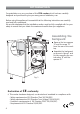
Conversion to Natural Gas or to LPG Injectors replacement of top burners J Every cooker is provided with a set of injectors for the various types of gas. Injectors not supplied can be obtained from the After-Sales Service. Select the injectors to be replaced according to the table at page 39. The nozzle diameters, expressed in hundredths of a millimetre, are marked on the body of each injector. To replace the injectors proceed as follows: – Remove the grids and extract the burner bodies.
Table for the choice of the injectors GB BURNERS Cat: Nominal Power Reduced Power [kW] [kW] G 20 20 mbar G 30 - 28-30 mbar G 31 - 37 mbar By-pass [1/100 mm] ring Ø injector Tube opening [1/100 mm] II 2H3+ [mm] By-pass Ø injector [1/100 mm] [1/100 mm] Tube ring opening [mm] 1,00 0,30 27 50 - 72 (X) - Semi-rapid (SR) 1,75 0,45 32 65 - 97 (Z) - adjustable Auxiliary (A) Rapid (R) 3,00 0,75 42 85 - Triple-ring 3,50 1,50 65 95 - Oven (left) 3,70 0,75 40 92 fully op
LEFT OVEN Oven burner and grill burner replacement of injectors a) oven burner Fig. 46 – Lift and remove the lower panel inside the oven. – Remove the burner securing screw (fig. 46). – Withdraw the burner as shown in figure 47 and rest it inside the oven. Take care not to damage the wire to the ignition electrode and the safety valve probe. – Using a 7 mm box spanner, unscrew the injector (indicated by the arrow in fig. 47) and replace it by the proper one according to the kind of gas.
Regulation of air supply to oven and grill burners Using a cross-head screwdriver, slacken the screw securing the air flow regulation collar (fig. 50 and 51) and move the collar forward or backward to increase or reduce the air aperture in accordance with gas type and the indications in the “TABLE FOR THE CHOICE OF THE INJECTORS”. Light the burner and check the flame. Fig. 51 Ring opening Fig.
RIGHT OVEN Oven burner and grill burner replacement of injectors a) oven burner Fig. 52 – Lift and remove the lower panel inside the oven. – Remove the 2 burner securing screws (fig. 52). – Withdraw the burner as shown in figure 53 and rest it inside the oven. Take care not to damage the wire to the ignition electrode and the safety valve probe. – Using a 7 mm box spanner, unscrew the injector (indicated by the arrow in fig. 53) and replace it by the proper one according to the kind of gas.
Regulation of air supply to oven and grill burners Using a screwdriver, slacken the screw securing the air flow regulation collar (fig. 56 and 57) and rotate the collar clockwise or anti-clockwise to increase or reduce the air aperture in accordance with gas type and the indications in the “TABLE FOR THE CHOICE OF THE INJECTORS”. Light the burner and check the flame. Fig. 57 Ring opening Fig.
LEFT and RIGHT OVENS Regulating of the oven minimum Considering that in the minimum position the flame must have a length of about 4 mm and must remain lit even with a brusque passage from the maximum position to that of minimum. To be effected only for the oven burner (as the grill burner has an only fixed input) operating on the thermostat as follows: – light the oven taking the knob to Max. position.
Lubrication of the gas taps The operations must be executed by a qualified technician. IMPORTANT All intervention regarding installation maintenance and conversion of the appliance must be fulfilled with original factory parts. The manufacturer declines any liability resulting from the non-compliance of this obligation.
Electrical installation For your safety please read the following information: This appliance must be installed by a qualified technician according with the current local regulations and in compliance with the manufacturer instructions. This appliance is supplied with a moulded 13 amp three pin mains plug with a 3 amp fuse fitted. Should the fuse require replacement, it must be replaced with a fuse rated at 3 amp and approved by ASTA or BSI to BS 1362.
Electrical feeder cable connection The operations must be executed by a qualified technician. To connect the supply cable: - Remove the screws securing the cover “A” on the rear of the cooker (fig. 60). - Feed the supply cable through the cable clamp “D”. The supply cable must be of a suitable size for the current requirements of the appliance; see the section “Feeder cable section”.
Appliance servicing CDA provide a quality and effective after-sales service to cover all your servicing needs. Please attach your receipt to this page for safekeeping. Please help us to help you by having the following information available when booking a service-call: 1. Model type, make and model – see the product data plate. 2. Evidence of installation / purchase date 3. Retailer where appliance was purchased 4. Clear and concise details of the fault 5.
Guarantee CDA appliances carry a five-year parts and a one-year labour guarantee. CDA will repair or replace any defect or part attributable to faulty material or workmanship. Within the first year this will be free of both labour and parts charges. After the first year and within five years, the parts will be supplied free of charge provided that the repair is carried out by an agent authorised by CDA and the labour will be charged at the commercial rate applicable at the time of repair.
Descriptions and illustrations in this booklet are given as simply indicative. The manufacturer reserves the right, considering the characteristics of the models described here, at any time and without notice, to make eventual necessary modifications for their construction or for commercial needs. Cod. 1103123 ß2 RC 9320 ..