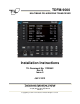
TDFM-9000 MULTIBAND P25 AIRBORNE TRANSCEIVER Installation Instructions TiL Document No. 11RE442 Rev. B Issue 5 JULY 2013 Technisonic Industries Limited 240 Traders Boulevard, Mississauga, Ontario L4Z 1W7 Tel: (905) 890-2113 Fax: (905) 890-5338 www.til.ca Copyright by Technisonic Industries Limited. All rights reserved.
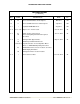
TECHNISONIC INDUSTRIES LIMITED REVISION HISTORY [ 11RE442 ] REV SECTION - PAGE - DATE EDITED BY A 2-5 Corrected Pin Numbers in Descriptions. Mar 2013 SM B iv Corrected DO-160 Version and Categories. July 2013 SM B–1 i Updated TDFM-9000 Photo. Aug 2013 SM B–2 2-7 to 2-10 Figures 2.2 – 2.5 Corrected. Oct. 28, 2013 AL B–3 2-1 All P/N in Section 2.4 Corrected. Corrected Spelling & Grammar throughout document. Jan. 27, 2014 AL B–4 iv Changed STC Approval Note.
TECHNISONIC INDUSTRIES LIMITED NOTES ESD CAUTION This unit contains static sensitive devices. Wear a grounded wrist strap and/or conductive gloves when handling printed circuit boards. FCC COMPLIANCE INFORMATION This device complies with Part 15 of the FCC Rules. Operation is subject to the following two conditions: (1) this device may not cause harmful interference and (2) this device must accept any interference received, including interference that may cause undesired operation.
TECHNISONIC INDUSTRIES LIMITED SUMMARY OF DO-160G ENVIRONMENTAL TESTING Summary of DO-160G Environmental Testing for Technisonic Model TDFM-9000 Transceiver: Conditions Category Temperature and Altitude A2, B1, C4, D1 Temperature Variation B Humidity A Operational Shock and Crash Safety A Vibration S, U Magnetic Effect Z Power Input B Voltage Spike B Audio Frequency Susceptibility B Induced Signal Susceptibility AC Radio Frequency Susceptibility T Radio Frequency Emission M Electr
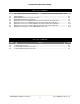
TECHNISONIC INDUSTRIES LIMITED TABLE OF CONTENTS SECTION SECTION 1 1.1 1.2 1.3 1.4 TITLE PAGE GENERAL DESCRIPTION B INTRODUCTION ..................................................................................................................... DESCRIPTION ........................................................................................................................ MODEL VARIATION ...............................................................................................................
TECHNISONIC INDUSTRIES LIMITED LIST OF FIGURES FIGURE 2.1 2.2 2.3 2.4 2.5 2.6 2.7 2.8 TITLE PAGE Outline Drawing ........................................................................................................................ TDFM-9000 Antenna & Connector Locations .......................................................................... TDFM-9000 Band Display Orientation .....................................................................................
TECHNISONIC INDUSTRIES LIMITED SECTION 1: GENERAL DESCRIPTION 1.1 INTRODUCTION This publication provides operating information on the TDFM-9000 airborne transceiver. The exact configuration depends on which and how many RF modules are installed. 1.2 DESCRIPTION The TDFM-9000 transceiver is an airborne multi-band radio capable of operation in conventional analog and P25 digital FM systems, SmartNet/SmartZone trunking systems, and P25 9600 trunking systems.
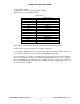
TECHNISONIC INDUSTRIES LIMITED Tray Breakdown: (TBB): T= Module type: A= T30xx RF modules (Single or Dual) B is Band code for each module in the tray. Band Codes 1 2 3 4 A B C D E F *G *H *I *J *K *L VHF (136-174) UHF LO (380-470) UHF HI (450-520) 700/800 (764-870) V/700/800 V/UHF LO V/UHF HI UL/UH UL/700/800 UH/700/800 700/800/V 700/800/UL 700/800/UH UHF LO/V UHF HI/V UH/UL Band numbers indicate single band modules and letters indicate dual band modules.
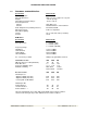
TECHNISONIC INDUSTRIES LIMITED 1.4 TECHNICAL CHARACTERISTICS Specification Characteristic Model Designation: Physical Dimensions: Weight: Operating Temperature Range: Power Requirement: Voltage: Current: Audio Output Power (including sidetone): Microphone Inputs: Panel Back Lighting: Voltage: Current: TDFM-9000 Approx. (L) 8.0" x (W) 5.75" x (H) 4.5" ~7.0 Lbs (3.2 Kg) -30° C to +60° C 28.0 VDC ± 15% 500 mA minimum / 7.
TECHNISONIC INDUSTRIES LIMITED SECTION 2: INSTALLATION INSTRUCTIONS 2.1 GENERAL This section contains information and instructions for the correct installation of the TDFM-9000 Transceiver. 2.2 EQUIPMENT PACKING LOG Unpack the equipment and check for any damage that may have occurred during transit. Save the original shipping container for returns due to damage or warranty claims. Check that each item on the packing slip has been shipped in the container. 2.
TECHNISONIC INDUSTRIES LIMITED FIGURE 2.1 Outline Drawing for Model TDFM-9000 TDFM-9000 Installation Instructions TiL 11RE442 Rev.
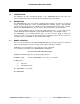
TECHNISONIC INDUSTRIES LIMITED ANT 5 ANT 6 ANT 1 ANT 2 J1 J5 ANT 4 J6 ANT 3 Figure 2.2 TDFM-9000 Antenna & Connector Locations BANDS 1 2 3 4 5 6 Figure 2.3 TDFM-9000 Band Display Orientation Band display corresponds to the antenna connector numbering and radio ports. Band 1 (top of the display) is connected the ANT 1 and uses the Band 1 connections on the interface connectors. TDFM-9000 Installation Instructions TiL 11RE442 Rev.
TECHNISONIC INDUSTRIES LIMITED 2.6 INSTALLATION - PIN LOCATIONS AND CONNECTIONS J1 (25 Pin D Connections) - Use FEMALE Connector Pin # Description 1 2 3 4 5 6 7 8 9 10 11 12 13 14 15 16 17 18 19 20 21 22 23 24 25 Ground Main Power +28 VDC Mic 1 Audio 1 PTT 1 Mic 2 Audio 2 PTT 2 Mic 3 Audio 3 PTT 3 TX Data RX Data Ground Main Power +28 VDC Up Down Channel / Band Mic 5 Audio 5 PTT 5 Mic 6 Audio 6 PTT 6 Panel Backlighting TABLE 2.
TECHNISONIC INDUSTRIES LIMITED J6 (15 Pin High Density D Connections) – Use FEMALE Connector Pin # Description 1 2 3 4 5 6 7 8 9 10 11 12 13 14 15 Ground Audio Combined 1 PTT4 PTT Combined 1 Audio 4 Mic 4 Mic Combined 1 Speaker Lo Speaker Hi Audio Combined 2 Misc In PTT Combined 2 Mic Combined 2 Misc In/Out Audio Combined Ground 2 TABLE 2.
TECHNISONIC INDUSTRIES LIMITED 2.7 INSTALLATION - WIRING INSTRUCTIONS Figure 2-2(a, b, and c) show all required connections and recommended wire sizes for the TDFM9000 transceiver. The TDFM-9000 allows for either a single audio output ground or separate grounds for each audio output. If a single point ground is required for a pre-existing installation, the dongle supplied in the installation kit must be plugged into J5.
TECHNISONIC INDUSTRIES LIMITED 2.14 PTT 1, 2, 3, 5, 6, AND 4 – J1 PINS 5, 8, 11, 21, 24, AND J6 PIN 3 There are individual PTT lines for each band. These lines should be floating when in receive and grounded for transmit. The input has a pull up resistor to 5 volts. Connecting an audio panel that wishes to see more may result in no receive audio. Connect a 1N4006 diode in series with the cathode towards the audio panel in this case. 2.
TECHNISONIC INDUSTRIES LIMITED FIGURE 2.4 Wiring Connections for Individual Band Control with Separate Ground Returns TDFM-9000 Installation Instructions TiL 11RE442 Rev.
TECHNISONIC INDUSTRIES LIMITED FIGURE 2.5 Wiring Connections for Individual Band Control with a Single Ground Return TDFM-9000 Installation Instructions TiL 11RE442 Rev.
TECHNISONIC INDUSTRIES LIMITED FIGURE 2.6 Wiring Connections for Combined Band Control with Separate Ground Returns TDFM-9000 Installation Instructions TiL 11RE442 Rev.
TECHNISONIC INDUSTRIES LIMITED FIGURE 2.7 Wiring Connections for Combined Band Control with a Single Ground Return TDFM-9000 Installation Instructions TiL 11RE442 Rev.
TECHNISONIC INDUSTRIES LIMITED FIGURE 2.8 Wiring Connection Notes for the TDFM-9000 Transceiver TDFM-9000 Installation Instructions TiL 11RE442 Rev.
TECHNISONIC INDUSTRIES LIMITED 2.21 ANTENNA SELECTION AND INSTALLATION CONSIDERATIONS Antenna installations will vary according to the number / type of bands installed in the TDFM9000, types of antennas selected, and space available on the aircraft. The materials list above contains many but not all antennas available. If dual band RF modules are installed in the TDFM9000, it is suggested to use a single connector, multiband antenna for each of the RF modules installed.
TECHNISONIC INDUSTRIES LIMITED RESULTS If the installed system passes all of the applicable EMI tests, then no further action is required. If interference is observed, then the interference must be assessed against the appropriate standards of airworthiness for the system in question.
TECHNISONIC INDUSTRIES LIMITED B. Determine if the image frequency for the VHF Comm falls within the range of the TDFM9000. If so, select a set of frequencies that will cause the TDFM-9000 to be set as close as possible to the image frequency. Any one of the many possible sets will suffice. Record those values in the spaces provided in the following chart. Modulate the TDFM9000 transmitter on the following frequencies for at least 20 seconds. Listen for any noise or detected audio signals on the VHF comm.
TECHNISONIC INDUSTRIES LIMITED C. Determine if the image frequency for the VOR/ILS Nav falls within the range of the TDFM9000. If so, select two sets of frequencies that will cause the TDFM-9000 to be set as close as possible to the image frequency. Choose one set in the localizer frequency range and one in the VOR frequency range. Record those values in the spaces provided in the following chart. Modulate the TDFM-9000 transmitter on the following frequencies for at least 20 seconds.
TECHNISONIC INDUSTRIES LIMITED D. The following procedure checks for second harmonic interference to the glide slope receiver from the TDFM-9000. All transceivers produce harmonics (multiples of the wanted frequency) and while the TDFM-9000 far exceeds FCC requirements, interference can still be experienced depending upon antenna position and separation.
TECHNISONIC INDUSTRIES LIMITED FREQUENCIES RESULTS G/S #1 TDFM-9000 334.7 (108.1) 167.35 PASS FREQUENCIES FAIL RESULTS G/S #2 TDFM-9000 334.7 (108.1) 167.35 PASS FAIL NOTES: E. Operate the TDFM-9000 transmitter on the following frequency for at least 20 seconds. Observe the Transponder for any spurious replies or loss of reply to test set. FREQUENCIES TDFM-9000 TRANSPONDER #1 PASS FAIL TRANSPONDER #2 PASS FAIL 512 MHz NOTES: TDFM-9000 Installation Instructions TiL 11RE442 Rev.
TECHNISONIC INDUSTRIES LIMITED F. Modulate the TDFM-9000 transmitter on the following frequencies for at least 20 seconds. Observe the DME displays. Look for loss of distance information on the display. FREQUENCIES RESULTS DME 1 TDFM-9000 978 (108.0) 489 1020 (112.1) 510 FREQUENCIES PASS FAIL RESULTS DME 2 TDFM-9000 978 (108.0) 489 1020 (112.1) 510 PASS FAIL NOTES: TDFM-9000 Installation Instructions TiL 11RE442 Rev.
TECHNISONIC INDUSTRIES LIMITED G. NOTE: For the following tests, select a frequency at the top, middle, and bottom of each band of the TDFM-9000 transceiver. 136 to 174 MHz Band 403 to 470 MHz Band 450 to 512 MHz Band 806 to 870 MHz Band Frequency #1 Frequency #2 Frequency #3 H. At a safe altitude, engage the autopilot or stability augmentation system. Modulate the TDFM-9000 transmitter on the above frequencies for at least 20 seconds.
TECHNISONIC INDUSTRIES LIMITED List the power plant, fuel and other electric instruments in the chart provided and note any anomalies that occur while transmitting. Assess the results. J.
TECHNISONIC INDUSTRIES LIMITED 13 Fuel % 14 Ng 15 TOT 16 Torque % 17 Annunciators 18 Digital Clock 19 Oil Pressure 20 DME 1 & 2 (VHF, UHF Lo, and 800 MHz) 21 GPS 1 & 2 (UHF Lo and 800 MHz) TDFM-9000 Installation Instructions TiL 11RE442 Rev.
TECHNISONIC INDUSTRIES LIMITED STEP SYSTEM PASS FAIL NOTES NOTES: TDFM-9000 Installation Instructions TiL 11RE442 Rev.
TECHNISONIC INDUSTRIES LIMITED APPENDIX A SUPPORT NOTES • For the latest Service Bulletin(s) refer to the Publication Index list under the section for this model (login required). • For the latest Technical Information Bulletins refer to the Publication Index list under the section for this model (login required). • For the latest Software Release(s) refer to the Publication Index list under the section for this model’s software/firmware history index (login required).
TECHNISONIC INDUSTRIES LIMITED Technisonic Industries Limited 240 Traders Blvd., Mississauga, ON Canada L4Z 1W7 Tel: (905) 890-2113 Fax: (905) 890-5338 IMPORTANT WARRANTY All communication equipment manufactured by Technisonic Industries Limited is warranted to be free of defects in Material or Workmanship under normal use for a period of one year from Date of Purchase by the end user.