
Operating instructions

TECHNISONIC INDUSTRIES LIMITED
TDFM-9000 Installation Instructions TiL 11RE442 Rev. B Issue 5
2-15
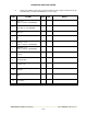
B. Determine if the image frequency for the VHF Comm falls within the range of the TDFM-
9000. If so, select a set of frequencies that will cause the TDFM-9000 to be set as close
as possible to the image frequency. Any one of the many possible sets will suffice.
Record those values in the spaces provided in the following chart. Modulate the TDFM-
9000 transmitter on the following frequencies for at least 20 seconds. Listen for any noise
or detected audio signals on the VHF comm.
Example - Bendix/King KY 196A:
The first IF frequency is 11.4 MHz. The L.O. is above the received frequency (high side
injection); therefore, the image frequency is 22.8 MHz above the selected frequency. Set
the KY 196A to 120.000 MHz and the TDFM-9000 to 142.8000 MHz.
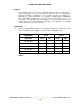
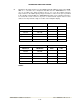
FREQUENCIES RESULTS
VHF #1 TDFM-9000 PASS FAIL
135.975 136.0000
121.150 157.5000
131.250 157.5000
Image:
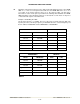
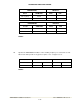
FREQUENCIES RESULTS
VHF #2 TDFM-9000 PASS FAIL
135.975 136.0000
121.150 157.5000
131.250 157.5000
Image:
NOTES: