RC 9322 .. Twin Cavity Gas Cooker Manual for Installation, Use and Maintenance GB Customer Care Department • The Group Ltd. • Harby Road • Langar • Nottinghamshire • NG13 9HY T : 01949 862 012 F : 01949 862 003 E : service@cda.eu W : www.cda.
Important This appliance is designed and manufactured solely for the cooking of domestic (household) food and is not suitable for any non domestic application and therefore should not be used in a commercial environment. The appliance guarantee will be void if the appliance is used within a non domestic environment i.e. a semi commercial, commercial or communal environment. The CDA Group Ltd cannot be held responsible for injuries or losses caused by incorrect use or installation of this product.
IMPORTANT SAFETY PRECAUTIONS AND RECOMMENDATIONS IMPORTANT: This appliance is designed and manufactured solely for the cooking of domestic (household) food and is not suitable for any non domestic application and therefore should not be used in a commercial environment. The appliance guarantee will be void if the appliance is used within a non domestic environment i.e. a semi commercial, commercial or communal environment. Read the instructions carefully before installing and using the appliance.
• • • • • • • • • • • • 4 Do not use a steam cleaner because the moisture can get into the appliance thus make it unsafe. Do not touch the appliance with wet or damp hands (or feet). Do not use the appliance whilst in barefoot.
• • • • • • • • • • • • • WARNING: Danger of fire: do not store items on the cooking surfaces. WARNING: When correctly installed, your product meets all safety requirements laid down for this type of product category. However special care should be taken around the rear or the underneath of the appliance as these areas are not designed or intended to be touched and may contain sharp or rough edges, that may cause injury.
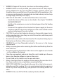
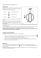
Features and Technical Data 2 4 3 1 2 1 Right Gas oven Fig. 1 Left Gas oven GAS BURNERS 1. Auxiliary burner (A) 1,00 kW 2. Semi-rapid burner (SR) 1,75 kW 3. Rapid burner (R) 3,00 kW 4. Triple-ring burner (TR) 3,50 kW Important Notes: –– –– 6 The electric ignition is incorporated in the knobs. The appliance has a safety valve system fitted, the flow of gas will be stopped if and when the flame should accidentally go out.
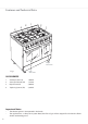
Control Panel Fig. 2 1 2 3 4 5 6 7 8 9 10 11 Controls Description 1. Left gas oven/gas grill control knob 2. Left oven light control knob 3. Minute counter 4. Right oven rotisserie / light control knob 5. Front left burner control knob 6. Rear left burner control knob 7. Front central burner control knob 8. Rear central burner control knob 9. Rear right burner control knob 10. Front right burner control knob 11.
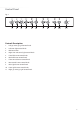
Minute Counter Minute Counter The minute counter is a timed acoustic warning device which can be set for a maximum of 60 minutes. The knob (Fig. 3) must be rotated clockwise as far as the 60 minute position and then set to the required time by rotating it anticlockwise. IMPORTANT WARNING: This is only a mechanical timer. Remember to turn off the oven/grill manually. Fig.
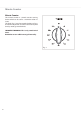
How to Use the Hob Burners Hob Burners Each hob burner is controlled by a separate gas valve operated by a control knob (fig. 4) which has 3 positions marked on the control panel, these are: – Symbol : Tap closed (burner off ) – Symbol : High (maximum) – Symbol : Low (minimum) Push in and turn the knob anti-clockwise to the selected position.
Choice of Burner The burner must be choosen according to the diameter of the pans and energy required. Saucepans with handles which are excessively heavy, in relationship to the weight of the pan, are safer as they are less likely to tip. Pans which are positioned centrally on burners are more stable than those which are offset. It is far safer to position the pan handles in such a way that they cannot be accidentally knocked. Fig. 5 When deep fat frying fill the pan only one third full of oil.
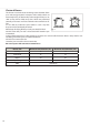
CORRECT USE OF TRIPLE-RING BURNER • Flat-bottomed pans are to be placed directly onto the pan-support. • To use the WOK, you must place the wok stand in the CORRECT position as shown in figs. 6 - 7. IMPORTANT The special grille for wok pans (fig. 7) MUST BE PLACED ONLY over the pan-rest for the triple-ring burner. CORRECT WRONG Fig. 6 Fig.
How to use the gas oven (left oven) General Features The oven is furnished completely clean; it is advisable, however, upon first use, to turn ) to eliminate possible traces the oven on to the maximum temperature (position of grease from the oven burner. The same operation should be followed for grill burner. The gas oven is provided with two burners: a. Oven burner, mounted on the lower part of the oven (wattage: 3,70 kW) b. Grill burner, mounted on the upper part of the oven (wattage: 2,50 kW).
Lighting the oven gas burner The thermostat allows the automatic control of the temperature. The gas delivery to the oven burner is controlled by a two way thermostatic tap (oven and grill burners) with flame-failure device. To light the oven burner operate as follow: 1. Open the oven door WARNING: Risk of explosion! The oven door must be open during this operation. 2. Lightly press and turn the thermostat knob anti-clockwise to max position “ 3.
How to use the gas grill (left oven) Lighting the grill gas burner The grill burner generates the infra-red rays for grilling. To light the grill burner operate as follow: 1. Open the oven door. WARNING: Risk of explosion! The oven door must be open during this operation. 2. Lightly press and turn the thermostat knob clockwise to the 11). 3. Press the knob right down to prime the electric ignition.
Use of the grill Very important: the grill must always be used with the oven door slightly open and with shield “A” mounted (Fig. 14). Mount shield “A” which serves to protect the control panel from the heat. Turn on the grill, as explained in the preceding paragraphs and let the oven preheat for about 5 minutes with the door ajar. Introduce the food to be cooked, positioning the rack as close to the grill as possible. The dripping pan should be placed under the rack to catch the cooking juices and fats.
How to use the gas oven (right oven) General features The oven is furnished completely clean; it is advisable, however, upon first use, to turn the oven on to the maximum temperature (position ) to eliminate possible traces of grease from the oven burner. The same operation should be followed for grill burner. Attention: the oven door becomes very hot during operation. Keep children away. The gas oven is provided with two burners: a.
Lighting the oven gas burner The thermostat allows the automatic control of the temperature. The gas delivery to the oven burner is controlled by a two way thermostatic tap (oven and grill burners) with flame-failure device. To light the oven burner operate as follows: 1. Open the oven door WARNING: Risk of explosion! The oven door must be open during this operation. 2. Lightly press and turn the thermostat knob anti-clockwise to max position “ 3.
How to use the gas grill (right oven) Lighting the grill gas burner The grill burner generates the infra-red rays for grilling. To light the grill burner operate as follow: 1. Open the oven door. WARNING: Risk of explosion! The oven door must be open during this operation. 2. Lightly press and turn the thermostat knob clockwise to the 18). 3. Press the knob right down to prime the electric ignition.
Use of the grill T O H Mount shield “A” which serves to protect the control panel from the heat. Turn on the grill, as explained in the preceding paragraphs and let the oven preheat for about 5 minutes with the door ajar. Introduce the food to be cooked, positioning the rack as close to the grill as possible. The dripping pan should be placed under the rack to catch the cooking juices and fats.
Rotisserie (right oven) This is used for spit roasting under the grill and comprises: • an electric motor fitted to the rear of the oven • a stainless steel skewer provided with slide-out heat-resistant handgrip and two sets of adjustable forks • a skewer support to be fitted in the middle runner. The rotisserie motor is operated by a control knob (Fig. 22). Fig. 22 Use of the rotisserie Very important: the rotisserie must always be used with the oven door ajar and with shield “A” mounted (Fig. 21).
Oven cooking temperatures MARK APPROX. TEMP. HEAT OF OVEN 130 130°C Very cool oven Meringue cakes, slow cooking items 140°C Cool or slow oven Milk puddings, very rich fruit cakes, i.e., Christmas 155°C Cool or slow oven Stews, casseroles, braising, rich fruit cakes, i.e., Dundee 165°C Warm oven Biscuits, rich plain cakes i.e., Madeira. Low temp.
Do’s and do not’s • • • • • • • • • • • • • • • • • • Do always grill with the oven door closed. Do read the user instructions carefully before using the cooker for first time. Do allow the oven to heat for one and a half hours, before using for the first time, in order to expel any smell from the new oven insulation, without the introduction of food. Do clean your oven regularly. Do remove spills as soon as they occur. Do always use oven gloves when removing food shelves and tray from the oven.
Care and Maintenance It is advisable to clean when the appliance is cold and especially for cleaning the enamelled parts. Avoid leaving alkaline or acidic substances (lemon juice, vinegar, etc.) on the surfaces. Avoid using cleaning products with a chlorine or acidic base. WARNING When correctly installed, your product meets all safety requirements laid down for this type of product category.
Changing the Oven Light 1. Disconnect the electrical power supply (for example, by switching off the main power switch). 2. Unscrew the light cover 3. Fit a new bulb. 4. Refit the cover. Note: Use only bulbs designed to resist up to 300°C with the following characteristics: 230 V, type E14 and same power (check watt power as stamped in the bulb itself ) of the replaced bulb. Burners and Grids • These parts can be removed and cleaned with appropriate products.
C F T S Fig. 24 Fig. 25 T S Fig. 26 A Fig. 27 B Fig.
Removal of the Inner Glass Door Panel • The inner glass door panel can easily be removed for cleaning by unscrewing the fixing screws (fig. 29). • When re-assembling ensure that the inner glass is correctly positioned and do not over tighten the screws. Do not use harsh abrasive cleaners or sharp metal scrapers to clean the oven door glass since they can scratch the surface, which may result in shattering of the glass. Fig.
Assembling and Dismantling of the Side Runner Frames • Fit the side runner frames into the holes on the side walls inside the oven (Fig. 31). • Slide into the guides, the shelf and the tray (left main oven only) (fig. 32). The rack must be fitted so that the safety notch, which stops it sliding out, faces the inside of the oven. • To dismantle, operate in reverse order. Fig. 31 Fig.
Oven Doors Removing the Oven Doors The oven door can easily be removed as follows: • Open the door to the full extent (fig. 33a). • Open the lever “A” completely on the left and right hinges (fig. 33b). • Hold the door as shown in fig. 33. • Gently close the door (fig.33c) until left and right hinge levers “A” are hooked to part “B” of the door (fig. 33b). • Withdraw the hinge hooks from their location following arrow “C” (fig. 33d). • Rest the door on a soft surface.
For the Installer Location The appliance may be installed in a kitchen, Kitchen/diner or a bed sitting room, but not in a room or space containing a bath or a shower. The appliance must not be installed in a bed-sitting room of less than 20m3. The appliance is designed and approved for domestic use only and should not be installed in a commercial , semi commercial or communal environment.
Assembling the Backguard • Remove the two spacers “A” and the screw “B” from the rear of the cooktop. • Assemble the backguard as shown in figure 35 and fix it by screwing the central screw “B” and the spacers “A”. C B A Fig.
Fitting the Adjustable Feet • The adjustable feet must be fitted to the base of the cooker before use. • Rest the rear of the cooker an a piece of the polystyrene packaging exposing the base for the fitting of the feet. • Fit the 4 legs by screwing them tight into the support base as shown in picture 36. WARNING When raising cooker to upright position always ensure two people carry out this manoeuvre to prevent damage to the adjustable feet (fig. 37). Fig. 36 Fig.
Warning To move the cooker always ensure two people carry out this manoeuvre to prevent damage to the appliance (fig. 38). Warning Be careful: do not lift the cooker by the door handles (fig. 39). Warning When moving cooker to its final position DO NOT DRAG (fig. 40). Lift feet clear of floor (fig. 38). Fig. 38 Levelling the Cooker The cooker may be levelled by screwing the lower ends of the feet IN or OUT (fig. 41). Fig. 39 Fig. 41 32 Fig.
Stability Bracket We recommend a stability bracket is fitted to the cooker. The type shown in fig. 42 can be purchased from most plumbers merchants and do it yourself (D.I.Y.) shops. Existing slot in rear of cooker Brackets Dotted line showing the position of cooker when fixed Fig. 42 3 Outline of cooker backplate at the engagement slot Wall fixing Floor fixing Fig.
Provision for Ventilation • The appliance should be installed into a room or space with an air supply in accordance with BS 5440-2: 2000. • For rooms with a volume of less than 5 m3 - permanent ventilation of 100 cm2 free area will be required. • For rooms with a volume of between 5 m3 and 10 m3 a permanent ventilation of 50 cm2 free area will be required unless the room has a door which opens directly to the outside air in which case no permanent ventilation is required.
Gas Installation Important Note This appliance is supplied for use on NATURAL GAS or LPG (check the gas regulation label attached on the appliance). • Appliances supplied for use on NATURAL GAS: they are adjusted for this gas only and cannot be used on any other gas (LPG) without modification. The appliances are manufactured for conversion to LPG. • Appliances supplied for use on LPG: they are adjusted for this gas only and cannot be used on any other gas (NATURAL GAS) without modification.
Gas Connection The installation of the gas appliance to Natural Gas or LP Gas must be carried out by a suitably qualified and registered installer. Installers shall take due account of the provisions of the relevant British Standards Code of Practice, the Gas Safety Regulations and the Building Standards (Scotland) (Consolidation) Regulations issued by the Scottish Development Department. Installation to Natural Gas Installation to Natural Gas must conform to the Code of Practice, etc.
Gas Connection GB Cat: II 2H3+ The gas supply must use the nearest gas inlet pipe which is located at the left or the right hand side at the rear of the appliance (fig. 45). The hose should also be connected in such a way that it does not touch the floor. To screw the connecting tube operate with two spanners (fig. 44). The unused end inlet pipe must be closed with the plug interposing the gasket.
Important Prescriptions for Gas Connection 700 mm Rear wall 200 mm Suggested area for gas mains connection Fig.
Conversion to Natural Gas or to LPG Injectors Replacement of Top Burners Every cooker is provided with a set of injectors for the various types of gas. Injectors not supplied can be obtained from the After-Sales Service. Select the injectors to be replaced according to the table at page 47. The nozzle diameters, expressed in hundredths of a millimetre, are marked on the body of each injector. To replace the injectors proceed as follows: • Remove the pan supports, the burner caps and flame speaders.
GB Cat: II 2H3+ Table for the Choice of the Injectors Nominal Power kW Reduced Power kW Auxiliary (A) 1,00 Semi-Rapid (SR) Rapid (R) Burners G30 - 28-30 mbar G31 - 37 mbar G20 - 20 mbar Ø Injector 1/100 mm Tube ring opening [mm] Ø Injector 1/100 mm Tube ring opening [mm] 0,30 50 - 72 (X) - 1,75 0,45 65 - 97 (Z) - 3,00 0,75 85 - 115 (Y) - Triple Ring (TR) 3,50 1,50 95 - 135 (T) - Oven (left) 3,70 0,75 92 fully open 140 5 Grill (left) 2,50 - 80 fully open 120
OPERATIONS TO BE EXECUTED FOR THE REPLACEMENT OF THE INJECTORS OF THE OVEN AND GRILL BURNERS Some models are provided with a set of injectors for the various types of gas. If the injectors are not supplied they can be obtained from the “Service Centre”. Select the injectors to be replaced according to the “Table for the choice of the injectors” (for the gas category check the data label attached on the appliance).
GRILL BURNER • Unscrew and remove the burner securing screw “A” (fig. 52). • Withdraw the burner as shown in figure 53. Take care not to damage the safety valve probe and the electric ignition electrode. • Using a 7 mm box spanner, unscrew the injector (indicated by the arrow in fig. 53) and replace it with a new one selected in accordance with the “Table for the choice of the injectors”.
REGULATION OF AIR SUPPLY TO OVEN AND GRILL BURNERS To regulate the air supply it is necessary to remove the burners from their housings (figs. 51 - 53). • Using a cross-head screwdriver, slacken the screws “A” securing the air flow regulation collar “B” (fig. 54) and move the collar forward or backward to increase or reduce the air aperture in accordance with gas type and the indications in the “Table for the choice of the injectors”.
Regulating of the oven minimum Considering that in the minimum position the flame must have a length of about 4 mm and must remain lit even with a rapid shift from the maximum position to that of minimum. To be effected only for the oven burner (as the grill burner only has a fixed input) operating on the thermostat as follows: • light the oven taking the knob to Max. position.
IMPORTANT: The cooker must be installed in accordance with the manufacturer’s instructions. Incorrect installation, for which the manufacturer accepts no responsibility, may cause damage to persons, animals and things. The connection of the appliance to earth is mandatory. The manufacturer declines all responsibility for any inconvenience resulting from the inobservance of this condition.
Electrical Installation WARNING! Electricity can be extremely dangerous. This appliance must be earthed. Electrical Feeder Cable Connection To connect the supply cable: • Remove the screw securing the cover “A” on the rear of the cooker (fig. 57). • Unscrew cable clamp “D” (Fig. 58). • Connect the wires to the terminal block “B” as shown in the diagram in figure 59. • Take up any slack in the cable and secure with the cable clamp “D”. • Replace the cover “A”.
Appliance Servicing CDA provide a quality and effective after-sales service to cover all your servicing needs. Please attach your receipt to this page for safekeeping. Please help us to help you by having the following information available when booking a service-call: 1. Model type, make and model – see the product data plate. 2. Evidence of installation / purchase date. 3. Retailer where appliance was purchased. 4. Clear and concise details of the fault. 5.
Cod. 1104237 - ß3 Please contact our Customer Care Department, or for Service on the details below. Customer Care Department • The Group Ltd. • Harby Road • Langar • Nottinghamshire • NG13 9HY T : 01949 862 012 F : 01949 862 003 E : service@cda.eu W : www.cda.