RC 9621 .. Twin Cavity Ceramic Cooker Manual for Installation, Use and Maintenance Customer Care Department • The Group Ltd. • Harby Road • Langar • Nottinghamshire • NG13 9HY T : 01949 862 012 F : 01949 862 003 E : service@cda.eu W : www.cda.
Important This appliance is designed and manufactured solely for the cooking of domestic (household) food and is not suitable for any non domestic application and therefore should not be used in a commercial environment. The appliance guarantee will be void if the appliance is used within a non domestic environment i.e. a semi commercial, commercial or communal environment. The CDA Group Ltd cannot be held responsible for injuries or losses caused by incorrect use or installation of this product.
IMPORTANT SAFETY PRECAUTIONS AND RECOMMENDATIONS IMPORTANT: This appliance is designed and manufactured solely for the cooking of domestic (household) food and is not suitable for any non domestic application and therefore should not be used in a commercial environment. The appliance guarantee will be void if the appliance is used within a non domestic environment i.e. a semi commercial, commercial or communal environment. Read the instructions carefully before installing and using the appliance.
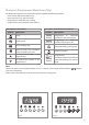
– Do not use a steam cleaner because the moisture can get into the appliance thus make it unsafe. – Do not touch the appliance with wet or damp hands (or feet). – Do not use the appliance whilst in barefoot.
– Make sure that electrical cables connecting other appliances in the proximity of the cooker cannot come into contact with the hob or become entrapped in the oven door. – WARNING: Unattended cooking on a hob with fat or oil can be dangerous and may result in fire. NEVER try to extinguish a fire with water, but switch off the appliance and then cover flame e.g. with a lid or a fire blanket. – WARNING: Danger of fire: do not store items on the cooking surfaces.
– CAUTION: Do not use harsh abrasive cleaners or sharp metal scrapers to clean the oven door glass since they can scratch the surface, which may result in shattering of the glass. – Do not line the oven walls with aluminium foil. Do not place baking trays or the drip tray on the base of the oven chamber. – FIRE RISK! Do not store flammable material in the oven or in the storage compartment. – Always use oven gloves when removing the shelves and food trays from the oven whilst hot.
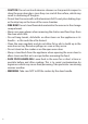
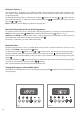
Features and Technical Data Vitroceramic Cooking Hob 1. 3 circuits cooking zone Ø 180 mm 2. 3 circuits cooking zone Ø 145 mm 3. Oval cooking zone Ø 145 x 250 mm 4. Double cooking zone Ø 210/120 mm 5. 3 circuits cooking zone Ø 145 mm 6. Cooking zone residual heat indicators 1700 W 1200 W 1800/1000 W 2100/700 W 1200 W Attention: Detach the appliance from the mains if the ceramic hob is cracked and contact CDA Customer Care. 3 6 4 1 5 2 Conventional oven Fig.
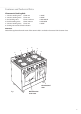
Control Panel Controls Description 1. Front right cooking zone control knob 2. Rear right cooking zone control knob 3. Central cooking zone control knob 4. Rear left cooking zone control knob 5. Front left cooking zone control knob 6. Multifunction main oven switch control knob 7. Multifunction main oven thermostat control knob 8. Electronic programmer (main oven only) 9. Conventional oven thermostat control knob 10. Conventional oven switch control knob Pilot Lamps: 11.
Electronic Programmer (Main Oven Only) The electronic programmer is a device that groups together the following functions: – 24 hour clock with illuminated display – Timer (up to 23 hours and 59 minutes) – Programme for automatic oven cooking – Programme for semi-automatic oven cooking. Description of the buttons: Symbols Description Description of the illuminated symbols: Symbols AUTO Timer flashing Cooking time AUTO always lit Description Programmer in automatic position but not programmed.
Electronic Clock (fig. 4) The programmer is equipped with an electronic clock with illuminated numbers which indicates hours and minutes. Upon immediate connection of the oven or after a power cut, three zeros will flash on the programmer display. To set the correct time of day it is necessary to push the button and then the or button until you have set the correct time. In another way push simultaneously the two buttons and at the same time push the or button.
Automatic Oven Cooking To cook food automatically in the oven, it is necessary to: 1. Set the length of the cooking time 2. Set the end of the cooking time 3. Set the temperature and the oven cooking program. These operations are done in the following way: 1. Set the length of the cooking period by pushing the button and the button to increase, or decrease if you have passed the desired time (fig. 7). The AUTO and the symbol will illuminate. to 2.
Semi - Automatic Cooking This is used to switch the oven off automatically after the desired cooking time has elapsed. There are two ways to set the semi-automatic cooking function: 1. Set the length of time you need to cook the food by pushing the or to go backwards (Fig. 9). This sets the desired “stop” time. AUTO and the symbol will be on. button and the button to advance, or 2.
How to Use the Vitroceramic Hob The ceramic surface of the hob allows a fast transmission of heat in the vertical direction, from the heating elements underneath the ceramic glass to the pans sat on it. Important Note: The heating elements incorporate a thermolimiter that switches the element ON/OFF during use to prevent the ceramic glass from overheating.
Double and Oval Radiant Zones The heating element is formed of a coil of resistant material which reaches the working temperature quickly. Operation of the cooking zone is controlled by a continuous energy regulator from “1” to “12” (maximum temperature) (fig. 13). To turn on both zones of the double element, turn the double element knob fully clockwise to the position . To reduce the heat of the full double element, turn its knob anticlockwise to setting 12 or lower.
Cooking Hints Position Type of cooking 0 0 Switched OFF 1 1 2 2 For melting operations (of butter or chocolate). 2 2 3 4 4 3 5 6 3 6 4 7 4 4 5 6 - 7 8 8 9 10 11 12 To keep foods warm or heat small quantities of water. Hob controlled by 7-position switch 1-6 Hob controlled by 12-position energy regulator 1 - 12 1 1 2 2 4 To heat greater quantities of water and to whip creams and sauces. Slow boiling, e.g.
Residual Heat Indicator The hob also features 5 warning lights which are connected to the corresponding plates. When the temperature of a cooking plate is above 60°C, the relevant warning light will also light up to warn of heat on the surface of the hob. This light stays on after the cooking plate has been switched off to show that the hob surface is still hot. This residual heat will last for a long time after the cooking plate has been switched off.
Safety Hints: – Before you switch the hob on, make sure you know which knob controls the required cooking plate. We advise you to set the pan over the cooking plate before switching it on. Remove the pan after you have switched the cooking plate off. – Do not use pots and pans with rough bases (pay attention to cookware made of cast-iron). Rough bases can damage (scratch) the glass surface of the hob. Make sure that the bottom of the pan is dry and clean.
How to Use the Multifunction Main Oven General Features As its name indicates, this is an oven that presents particular features from an operational point of view. In fact, it is possible to insert 7 different programmes to satisfy every cooking need. The 7 positions, thermostatically controlled, are obtained by 4 heating elements which are: – Bottom element 1200 W – Top element 1000 W – Grill element 2000 W – Circular element 2200 W Attention: The oven door becomes very hot during operation.
Thermostat Knob (fig. 20) This only sets the cooking temperature and does not switch the oven on. Rotate clockwise until the required temperature is reached (from 50 to 250°C). The light between the thermostat and the function selector will illuminate when the oven is switched on and turns off when the oven reaches the correct temperature. The light will cycle on and off during cooking in line with the oven temperature. Fig. 20 Fig. 21 Function Selector knob (fig.
Grilling The infrared grill element comes on. The heat is dispersed by radiation. Use with the oven door closed and the thermostat knob to position 225°C for max 15 minutes, then to position 175°C. For cooking hints, see the chapter “USE OF THE GRILL”. Recommended for: Intense grilling, browning, cooking au gratin and toasting etc. It is recommended that you do not grill for longer than 30 minutes at any one time. Caution: the oven door becomes very hot during operation. Keep children well out of reach.
Ventilated Grill Cooking The infrared grill element and the fan come on. The heat is dispersed mainly by radiation and the fan then distributes it all over the oven. Use with the door closed. The temperature can be regulated via the thermostat knob to between 50° and 175° max. The oven must be preheated for approximately 5 minutes. For cooking hints, see the chapter “GRILLING AND AU GRATIN. Recommended for: Grilling where quick browning on the outside is required to keep the juices in.
Cooking Advice Sterilization Sterilization of foods to be conserved, in full and hermetically sealed jars, is done in the following way: a. Set the switch to position . b. Set the thermostat knob to position 185 °C and preheat the oven. c. Fill the dripping pan with hot water. d. Set the jars onto the dripping pan making sure they do not touch each other and the door and set the thermostat knob to position 135 °C.
Roasting To obtain classical roasting, it is necessary to remember: – that it is advisable to maintain a temperature between 180° and 200 °C. – that the cooking time depends on the quantity and the type of foods. Use of the Grill – Preheat the oven for about 5 minutes. – Introduce the food to be cooked, positioning the rack as close to the grill as possible. – The dripping pan should be placed under the rack to catch the cooking juices and fats. Grilling with the oven door closed.
How to Use the Conventional Oven General Features As its name indicates, this is an oven that presents particular features from an operational point of view. The conventional oven is provided with 3 heating elements which are: – Bottom element 735 W – Top element 643 W – Grill element 1332 W Attention: The oven door becomes very hot during operation.
Function Selector Knob (fig. 22) Rotate the knob clockwise to set the oven for one of the following functions. Oven Light By setting the knob to this position, only the oven light comes on. It remains on in all the cooking modes. Traditional Convection Cooking The upper and lower heating elements come on. The heat is dispersed by natural convection and the temperature must be set to between 50° and 250°C via the thermostat knob. The oven must be preheated before cooking.
Use of the Grill Switch the grill on, setting the two knobs: – Function selector to or position. – Thermostat selector to position 225°C for 15 minutes then to 175°C. Leave to warm up for approximately 5 minutes with the door closed. Place the food inside positioning the rack as near as possible to the grill. Insert the drip pan under the rack to collect the cooking juices. Grilling with the oven door closed and do not for longer than 30 minutes at any one time.
Do’s and do not’s – Do always grill with the oven door closed. – Do read the user instructions carefully before using the cooker for first time. – Do allow the oven to heat for one and a half hours, before using for the first time, in order to expel any smell from the new oven insulation, without the introduction of food. – Do clean your oven regularly. – Do remove spills as soon as they occur. – Do always use oven gloves when removing food shelves and trays from the oven.
Care and Maintenance Important: As a safety measure, before you start cleaning the cooker be sure to disconnect it from the mains supply. – Do not use cleaning products with a chlorine or acidic base. – Do not use a steam cleaner because the moisture can get into the appliance thus make it unsafe. – The use of suitable protective clothing/gloves is recommended when handling or cleaning this appliance.
Removal of the Inner Glass Door Panel – The inner glass door panel can easily be removed for cleaning by unscrewing the four screws (fig. 25). – When re-assembly ensure that the inner glass is correctly positioned and do not over tighten the screws. Do not use harsh abrasive cleaners or sharp metal scrapers to clean the oven door glass since they can scratch the surface, which may result in shattering of the glass. Fig.
Inside of Oven The oven should always be cleaned after use when it has cooled down. The cavity should be cleaned using a mild detergent solution and warm water. Suitable proprietary chemical cleaners may be used after first consulting with the manufacturers recommendations and testing a small sample of the oven cavity. Abrasive cleaning agents or scouring pads/cloths should not be used on the cavity surface.
Removing the Oven Door The oven door can easily be removed as follows: – Open the door to the full extent (Fig. 29a). – Open the lever “A” completely on the left and right hinges (Fig. 29b). – Hold the door as shown in Fig. 29. – Gently close the door (fig. 24c) until left and right hinge levers “A” are hooked to part “B” of the door (fig. 29b). Fig. 29a – Withdraw the hinge hooks from their location following arrow “C” (Fig. 29d). – Rest the door on a soft surface.
FOR THE INSTALLER Location The appliance may be installed in a kitchen, Kitchen/diner or a bed sitting room, but not in a room or space containing a bath or a shower. The appliance must not be installed in a bed-sitting room of less than 20 m3. The appliance is designed and approved for domestic use only and should not be installed in a commercial, semi commercial or communal environment.
Assembling the Backguard Before installing the cooker, assemble the backguard "V" (fig. 31). Please note that : – The backguard "V" can be found packed at the rear of the cooker. – Before assembling remove any protective film/adhesive tape. – The backguard must be fixed to the cooktop using the three supports "B" supplied with the appliance (see fig. 31). B B A A VV Fig. 31 Fitting the Adjustable Feet – The adjustable feet must be fitted to the base of the cooker before use.
Warning To move the cooker always ensure two people carry out this manoeuvre to prevent damage to the appliance (fig. 34). Warning Be careful: do not lift the cooker by the door handle (fig. 35). Warning When moving cooker to its final position DO NOT DRAG (fig. 36). Lift feet clear of floor (fig. 34). Fig. 34 Levelling the Cooker The cooker may be levelled by screwing the lower ends of the feet IN or OUT (fig. 37). Fig. 35 Fig. 37 34 Fig.
ANTI-TILT BRACKET Important! To restrain the appliance and prevent it tipping accidentally, fit a bracket to its rear to fix it securely to the wall. To fit the anti-tilt bracket: 1. After you have located where the cooker is to be positioned, mark on the wall the place where the two screws of the anti-tilt bracket have to be fitted. Please follow the indications given in fig. 38. 2. Drill two 8 mm diameter holes in the wall and insert the plastic plugs supplied.
Electrical Installation IMPORTANT: The cooker must be installed in accordance with the manufacturer’s instructions. Incorrect installation, for which the manufacturer accepts no responsibility, may cause injury to persons, animals or equipment. For Your Safety Please Read the Following Information: – Connection to the mains must be carried out by qualified technician in accordance with current regulations.
Connecting the power cord must be entrusted to skilled personnel in accordance with the instructions supplied by the manufacturer and in compliance with established safety standards. Connecting the Mains Cable To connect the feeder cable to the cooker it is necessary to: – Remove the two screws that hold shield "A" behind the cooker. – Open completely the cable clamp "D". – Insert the mains cable (see FEEDER CABLE SECTION) into the cable clamp "D".
Appliance Servicing CDA provide a quality and effective after-sales service to cover all your servicing needs. Please attach your receipt to this page for safekeeping. Please help us to help you by having the following information available when booking a service-call: 1. Model type, make and model – see the product data plate. 2. Evidence of installation / purchase date 3. Retailer where appliance was purchased 4. Clear and concise details of the fault 5.
Cod. 1104252 - ß3 Please contact our Customer Care Department, or for Service on the details below. Customer Care Department • The Group Ltd. • Harby Road • Langar • Nottinghamshire • NG13 9HY T : 01949 862 012 F : 01949 862 003 E : service@cda.eu W : www.cda.