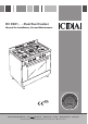
RC 9001 .. - Dual Fuel Cooker Manual for Installation, Use and Maintenance GB Customer Care Department • The Group Ltd. • Harby Road • Langar • Nottinghamshire • NG13 9HY T : 01949 862 012 F : 01949 862 003 E : service@cda.eu W : www.cda.
Important This appliance is designed and manufactured solely for the cooking of domestic (household) food and is not suitable for any non domestic application and therefore should not be used in a commercial environment. The appliance guarantee will be void if the appliance is used within a non domestic environment i.e. a semi commercial, commercial or communal environment. The CDA Group Ltd cannot be held responsible for injuries or losses caused by incorrect use or installation of this product.
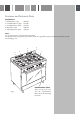
Features and Technical Data Gas Burners 1. Auxiliary burner (A) 2. Semi-Rapid burner (SR) 3. Semi-Rapid burner (SR) 4. Rapid burner (R) 5. Triple Ring burner (TR) 1.00 kW 1.75 kW 1.75 kW 3.00 kW 3.50 kW Note: The electric ignition is incorporated in the knobs. The appliance has a safety valve system fitted, the flow of gas will be stopped if and when the flame should accidentally go out. 5 2 4 3 1 Identification Label Fig.
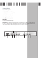
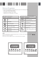
Control Panel Controls Description 1. Electronic programmer 2. Multifunction oven switch knob 3. Multifunction oven thermostat knob 4. Front left burner control knob 5. Rear left burner control knob 6. Central burner control knob 7. Rear right burner control knob 8. Front right burner control knob Pilot Lamp: 9. Oven thermostat indicator light Please note: This appliance incorporates a safety cooling fan which you will hear operating whenever the oven or grill are in use.
Electronic Programmer The electronic programmer is a device that groups together the following functions: – 24 hour clock with illuminated display – Timer (up to 23 hours and 59 minutes) – Programme for automatic oven cooking – Programme for semi-automatic oven cooking.
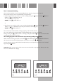
Electronic Clock (fig. 4) The programmer is equipped with an electronic clock with illuminated numbers which indicates hours and minutes. Upon immediate connection of the oven or after a power cut, three zeros will flash on the programmer display. To set the correct time of day it is necessary to push the button and then the or button until you have set the correct time (fig. 4). In another way push simultaneously the two buttons and at the same time push the or button.
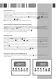
Automatic Oven Cooking To cook food automatically in the oven, it is necessary to: 1. Set the length of the cooking time 2. Set the end of the cooking time 3. Set the temperature and the oven cooking program. These operations are done in the following way: 1. Set the length of the cooking period by pushing the button and the decrease if you have passed the desired time (fig. 7). The AUTO and the button to increase, or to symbol will illuminate. 2.
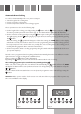
Semi - Automatic Cooking This is used to switch the oven off automatically after the desired cooking time has elapsed. There are two ways to set the semi-automatic cooking function: 1. Set the length of time you need to cook the food by pushing the advance, or to go backwards (Fig. 9). This sets the desired “stop” time. symbol will be on. AUTO and the button and the button to 2.
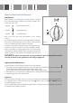
How to Use the Hob Burners Hob Burners Each hob burner is controlled by a separate gas valve operated by a control knob (fig. 11) which has 3 positions marked on the control panel, these are: – Symbol : tap closed (burner off) – Symbol : High (maximum) – Symbol : Low (minimum) Push in and turn the knob anti-clockwise to the selected position. The maximum aperture position permits rapid boiling of liquids, Fig.
Choice of Burner The burner must be choosen according to the diameter of the pans and energy required. Saucepans with handles which are excessively heavy, in relationship to the weight of the pan, are safer as they are less likely to tip. Pans which are positioned centrally on burners are more stable than those which are offset. It is far safer to position the pan handles in such a way that they cannot be accidentally knocked. Fig. 12 When deep fat frying fill the pan only one third full of oil.
How to Use the Multifunction Oven General Features As its name indicates, this is an oven that presents particular features from an operational point of view. In fact, it is possible to insert 7 different programmes to satisfy every cooking need. The 7 positions, thermostatically controlled, are obtained by 4 heating elements which are: – Bottom element 1725 W – Top element 1725 W – Grill element 2500 W – Circular element 2200 W Attention: The oven door becomes very hot during operation.
Thermostat Knob (fig. 16) This only sets the cooking temperature and does not switch the oven on. Rotate clockwise until the required temperature is reached (from 50 to 250°C). The light between the thermostat and the function selector will illuminate when the oven is switched on and turns off when the oven reaches the correct temperature. The light will cycle on and off during cooking in line with the oven temperature. Fig. 15 Function Selector Knob (fig.
Grilling The infrared grill element comes on. The heat is dispersed by radiation. Use with the oven door closed and the thermostat knob to position 225°C for max 15 minutes, then to position 175°C. For cooking hints, see the chapter “USE OF THE GRILL”. Recommended for: Intense grilling, browning, cooking au gratin and toasting etc. It is recommended that you do not grill for longer than 30 minutes at any one time. Caution: the oven door becomes very hot during operation. Keep children well out of reach.
Ventilated Grill Cooking The infrared grill element and the fan come on. The heat is dispersed mainly by radiation and the fan then distributes it all over the oven. Use with the door closed. The temperature can be regulated via the thermostat knob to between 50° and 175° max. The oven must be preheated for approximately 5 minutes. For cooking hints, see the chapter “GRILLING AND AU GRATIN. Recommended for: Grilling where quick browning on the outside is required to keep the juices in.
Cooking Advice Sterilization Sterilization of foods to be conserved, in full and hermetically sealed jars, is done in the following way: a. Set the switch to position . b. Set the thermostat knob to position 185 °C and preheat the oven. c. Fill the dripping pan with hot water. d. Set the jars onto the dripping pan making sure they do not touch each other and the door and set the thermostat knob to position 135 °C.
Roasting To obtain classical roasting, it is necessary to remember: – that it is advisable to maintain a temperature between 180° and 200 °C. – that the cooking time depends on the quantity and the type of foods. Use of the Grill – Preheat the oven for about 5 minutes. – Introduce the food to be cooked, positioning the rack as close to the grill as possible. – The dripping pan should be placed under the rack to catch the cooking juices and fats. Grilling with the oven door closed.
Do’s and do not’s – Do always grill with the oven door closed. – Do read the user instructions carefully before using the cooker for first time. – Do allow the oven to heat for one and a half hours, before using for the first time, in order to expel any smell from the new oven insulation, without the introduction of food. – Do clean your oven regularly. – Do remove spills as soon as they occur. – Do always use oven gloves when removing food shelves and trays from the oven.
Care and Maintenance Important: As a safety measure, before you start cleaning the cooker be sure to disconnect it from the mains supply. Do not use cleaning products with a chlorine or acidic base. Do not use a steam cleaner because the moisture can get into the appliance thus make it unsafe. The use of suitable protective clothing/gloves is recommended when handling or cleaning of this appliance.
Stainless Steel, Aluminium, Painted Parts and Silk-Screen Printed Surfaces Clean using an appropriate product. Always dry thoroughly. Stainless steel surfaces: can be cleaned with an appropriate stainless steel cleaner. IMPORTANT: these parts must be cleaned very carefully to avoid scratching and abrasion. You are advised to use a soft cloth and neutral soap. CAUTION: Do not use abrasive substances or non-neutral detergents as these will irreparably damage the surface. Changing the Oven Light 1.
Burners and Grids – These parts can be removed and cleaned with appropriate products. – After cleaning, the burners and their flame spreaders must be well dried and correctly replaced. – It is very important to check that the burner flame spreader and the cap have been correctly positioned. Failure to do so can cause serious problems. – Check that the electrode “S” (figs. 17-19) is always clean to ensure trouble-free sparking. – Check that the probe “T” (figs.
Correct Position of Triple Ring Burner The triple ring burner must be correctly positioned (see fig. 19); the burner ribs must be fitted in their housing as shown by the arrow. The burner correctly positioned must not rotate (fig. 20). Then position the cap A and the ring B (figs. 20 - 21) Flame failure probe “T” Ignitor “S” Fig. 19 A Fig. 20 B Fig.
Removal of the Inner Glass Door Panel – The inner glass door panel can easily be removed for cleaning by unscrewing the four screws (fig. 22). – When re-assembly ensure that the inner glass is correctly positioned and do not over tighten the screws. Do not use harsh abrasive cleaners or sharp metal scrapers to clean the oven door glass since they can scratch the surface, which may result in shattering of the glass. Fig.
Inside of Oven The oven should always be cleaned after use when it has cooled down. The cavity should be cleaned using a mild detergent solution and warm water. Suitable proprietary chemical cleaners may be used after first consulting with the manufacturers recommendations and testing a small sample of the oven cavity. Abrasive cleaning agents or scouring pads/cloths should not be used on the cavity surface.
Oven Tray The oven tray "L" must be correctly placed on the wire support (fig. 26) then inserted into the side runners (fig. 27). Oven Floor The oven floor “F” (fig. 27) can be easily removed to facilitate cleaning. Remember to replace the floor correctly afterwards. Be careful not to confuse the tray “L” with the oven floor “F”. L Fig. 26 L F Fig.
Removing the Oven Door Please operate as follows: – Open the door completely. – The swivel retainers of the rh and lh hinges (fig. 28a) are hooked onto the metal bar above them (fig. 28b). – Lift the oven door slightly. The noch on the bottom of the hinge will disengage (fig. 28c). – Now pull the oven door forwards off the appliance. Release both hinge sections from the slots (fig. 28d). Fig. 28a Fig.
FOR THE INSTALLER Location The appliance may be installed in a kitchen, Kitchen/diner or a bed sitting room, but not in a room or space containing a bath or a shower. The appliance must not be installed in a bed-sitting room of less than 20 m3. The appliance is designed and approved for domestic use only and should not be installed in a commercial, semi commercial or communal environment.
Assembling the Backguard – Remove the two spacers “A” and the screw “B” from the rear of the cooktop. – Assemble the backguard as shown in figure 30 and fix it by screwing the central screw “B” and the spacers “A”. B B A Fig. 30 Fitting the Adjustable Feet – The adjustable feet must be fitted to the base of the cooker before use. – Rest the rear of the cooker an a piece of the polystyrene packaging exposing the base for the fitting of the feet.
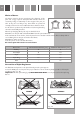
Warning To move the cooker always ensure two people carry out this manoeuvre to prevent damage to the appliance (fig. 33). Warning Be carefull: do not lift the cooker by the door handle (fig. 34). Warning When moving cooker to its final position DO NOT DRAG (fig. 35). Lift feet clear of floor (fig. 33). Fig. 33 Levelling the Cooker The cooker may be levelled by screwing the lower ends of the feet IN or OUT (fig. 36). Fig. 34 Fig. 36 Fig.
Stability Bracket We recommend a stability bracket is fitted to the cooker. The type shown in fig. 38 can be purchased from most plumbers merchants and do it yourself (D.I.Y.) shops. Existing slot in rear of cooker Brackets Dotted line showing the position of cooker when fixed Fig. 37 Fig.
Provision for Ventilation – The appliance should be installed into a room or space with an air supply in accordance with BS 5440-2: 2000. – For rooms with a volume of less than 5 m3 - permanent ventilation of 100 cm2 free area will be required. – For rooms with a volume of between 5 m3 and 10 m3 a permanent ventilation of 50 cm2 free area will be required unless the room has a door which opens directly to the outside air in which case no permanent ventilation is required.
Gas Installation Important Note This appliance is supplied for use on NATURAL GAS or LPG (check the gas regulation label attached on the appliance). – Appliances supplied for use on NATURAL GAS: they are adjusted for this gas only and cannot be used on any other gas (LPG) without modification. The appliances are manufactured for conversion to LPG. – Appliances supplied for use on LPG: they are adjusted for this gas only and cannot be used on any other gas (NATURAL GAS) without modification.
Gas Connection The installation of the gas appliance to Natural Gas or LP Gas must be carried out by a suitably qualified and registered installer. Installers shall take due account of the provisions of the relevant British Standards Code of Practice, the Gas Safety Regulations and the Building Standards (Scotland) (Consolidation) Regulations issued by the Scottish Development Department. Installation to Natural Gas Installation to Natural Gas must conform to the Code of Practice, etc.
Gas Connection Cat: II 2H3+ The gas supply must use the nearest gas inlet pipe which is located at the left or the right hand side at the rear of the appliance (fig. 39). The hose should also be connected in such away that it does not touch the floor. To screw the connecting tube operate with two spanners (fig. 40). The unused end inlet pipe must be closed with the plug interposing the gasket.
Important Prescriptions for Gas Connection 700 mm Rear wall 200 mm Suggested area for gas mains connection Fig.
Conversion to Natural Gas or to LPG Injectors Replacement of Top Burners Every cooker is provided with a set of injectors for the various types of gas. Injectors not supplied can be obtained from the After-Sales Service. Select the injectors to be replaced according to the table at page 36. The nozzle diameters, expressed in hundredths of a millimetre, are marked on the body of each injector. To replace the injectors proceed as follows: – Remove the grids and extract the burner bodies.
Table for the Choice of the Injectors Burners Nominal Power kW Cat: II 2H3+ Reduced Power kW G30 - 28-30 mbar G31 - 37 mbar G20 - 20 mbar Ø Injector 1/100 mm Ø Injector 1/100 mm Auxiliary (A) 1,00 0,30 50 72 (X) Semi-Rapid (SR) 1,75 0,45 65 97 (Z) Rapid (R) 3,00 0,75 85 115 (Y) Triple Ring (TR) 3,50 1,50 95 135 (T) Increase of Air Necessary for Gas Combustion (2 m3/h x kW) Burners Air necessary for combustion (m3/h) Auxiliary (A) 2,00 Semi-Rapid (SR) 3,50 Rapid (R) 6,00
Electrical Installation WARNING! Electricity can be extremely dangerous. This appliance must be earthed. The appliance must be connected to the electrical network verifying above all that the voltage corresponds to the value indicated on the specifications plate and that the cables section of the electrical plant can bear the load which is also indicated on the plate.
Connection to Fixed Wiring A double pole switch must be provided no further than 2 metres from the appliance to the electrical supply. The appliance should be connected to a DOUBLE POLE SWITCHED FUSED SPUR OUTLET, similar to that shown in Fig. 47. Fig. 47 DOUBLE POLE SWITCHED FUSED SPUR OUTLET FUSE ON use a suitable FUSE in accordance with the appliance power rating We recommend that the appliance is connected by a suitably qualified person who will comply with the IEE and local regulation.
Appliance Servicing CDA provide a quality and effective after-sales service to cover all your servicing needs. Please attach your receipt to this page for safekeeping. Please help us to help you by having the following information available when booking a service-call: 1. Model type, make and model – see the product data plate. 2. Evidence of installation / purchase date 3. Retailer where appliance was purchased 4. Clear and concise details of the fault 5.
Cod. 1103537 - ß2 To contact our Customer Care Department, or for Service, please contact us on the details below. Customer Care Department • The Group Ltd. • Harby Road • Langar • Nottinghamshire • NG13 9HY T : 01949 862 012 F : 01949 862 003 E : service@cda.eu W : www.cda.