Twin cavity ceramic cooker RC 9620 ..
Dear Customer Thank you for choosing one of our appliances, carefully designed and built by our specialist staff and thoroughly tested to satisfy your cooking requirements. We suggest that you read this Instruction Booklet so that you will understand fully how to operate your appliance. Please keep the booklet handy. You may wish to refer to it at a later date. CDA IMPORTANT INFORMATION FOR CORRECT DISPOSAL OF THE PRODUCT IN ACCORDANCE WITH EC DIRECTIVE 2002/96/EC.
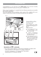
Contents Model RC 9620 .. Page Number Introduction . . . . . . . . . . . . . . . . . . . . . . . . . . . . . . . . . . . . . . . . . . . . . . 4 Assembling the backguard . . . . . . . . . . . . . . . . . . . . . . . . . . . . . . . . . . . . 4 Features and technical data . . . . . . . . . . . . . . . . . . . . . . . . . . . . . . . . . . . 5 Control panel . . . . . . . . . . . . . . . . . . . . . . . . . . . . . . . . . . . . . . . . . . . . . 6 Electronic programmer (main oven only) . . . . . . . . . . . .
Introduction Congratulations on your purchase of this CDA cooker which has been carefully designed and produced to give you many years of satisfactory use. Before using this appliance it is essential that the following instructions are carefully read and fully understood. We would emphasise that the installation section must be fully complied with for your safety to ensure that you obtain the maximum benefits from your appliance. Fig.
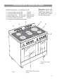
Features and technical data Vitroceramic cooking hob 1. 3 circuits cooking zone Ø 180 1700 W 2. 3 circuits cooking zone Ø 145 1200 W 3. Oval cooking zone Ø 145 x 250 1800/1000 W 4. Double cooking zone Ø 210/120 2100/700 W 5. 3 circuits cooking zone Ø 145 1200 W 6. Cooking zone residual heat indicators Attention: Detach the appliance from the mains if the ceramic hob is cracked and contact the After-Sales service. 4 3 5 1 2 6 Conventional oven Fig.
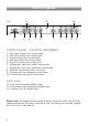
Control panel 13 11 Fig. 3 12 A U T O 8 7 6 5 4 3 2 1 10 9 Control panel - Controls description 1. Front right cooking zone control knob 2. Rear right cooking zone control knob 3. Central cooking zone control knob 4. Rear left cooking zone control knob 5. Front left cooking zone control knob 6. Multifunction main oven switch control knob 7. Multifunction main oven thermostat control knob 8. Electronic programmer (main oven only) 9. Conventional oven thermostat control knob 10.
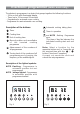
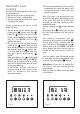
Electronic programmer (main oven only) The electronic programmer is a device that groups together the following functions: – 24 hour clock with illuminated display – Timer (up to 23 hours and 59 minutes) – Programme for automatic oven cooking – Programme for semi-automatic oven cooking.
Electronic clock (fig. 5) Electronic timer The programmer is equipped with an electronic clock with lighted numbers which indicate hours and minutes. Upon immediate connection of the oven or after a blackout, three zeroes will flash on the programmer panel. To set the hour it is necessary to push the button and then the or button until you have set the exact hour (fig. 5). Alternatively, simultaneously push the two buttons and at the same time push the or button.
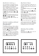
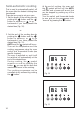
Automatic oven cooking To cook food automatically in the oven, it is necessary to: 1.Set the length of the cooking time 2.Set the end of the cooking time 3.Set the temperature and the oven cooking programme. These operations are done in the following way: 1.Set the length of the cooking time by pushing the button and the button to advance, or to go back if you have passed the desired time (fig. 8). The AUTO and the symbol will be on. 2.
Semi-automatic cooking This is used to automatically switch off the oven after the desired cooking time has elapsed. There are two ways to set your oven: 1. Set the length of the cooking time by pushing the button and the button to advance, or to go backwards if you have passed the desired time (Fig. 10). At the end of cooking, the oven and the symbol will turn off, the AUTO will flash and a buzzer will sound; that can be stopped by pushing any of the buttons.
How to use the vitroceramic hob The ceramic surface of the hob allows a fast transmission of heat in the vertical direction, from the heating elements underneath the ceramic glass to the pans sat on it. The heat does not spread in the horizontal direction, so that the glass stays “cool” at only a few centimeters from the cooking plate. The 5 cooking plates are shown by painted disks on the ceramic surface.
Double and oval radiant zones The heating element is formed of a coil of resistant material which reaches the working temperature quickly. Operation of the cooking zone is controlled by a continuous energy regulator from “1” to “12” (maximum temperature) (fig. 14). By switching on the second element (fig. 15 and 16), the surface area of the rear right and central radiant zones can be extended. For this purpose, turn the control knob (fig. 14) fully to the right (position ). Fig. 14 Second element Fig.
Cooking hints Cooking plate controlled by a 7 position switch Cooking plate controlled by a 12 position switch 1 1 2 Knob setting 0 0 Switched OFF 1 2 For melting operations (butter, chocolate). 4 1 2 2 2 3 4 To maintain food hot and to heat small quantities of liquid (sauces, eggs). 4 5 6 To heat bigger quantities; to whip creams and sauces. (vegetables, fruits, soups). 3 6 4 7 Slow boiling, i.e.: boiled meats, spaghetti, soups, continuations of steam cooking of roasts, stews, potatoes.
Residual heat indicator The hob also features 5 warning lights which are connected to the corresponding plates. When the temperature of a cooking plate is above 60°C, the relevant warning light will also light up to warn of heat on the surface of the hob. This light also stay on after the cooking plate has been switched off to show that the hob surface is still hot. This residual heat will lasts for a long time after the cooking plate has been switched off.
Safety hints: Cleaning the hob – Before you switch the hob on, make sure you know which knob controls the required cooking plate. We advise you to set the pan over the cooking plate before switching it on. Remove the pan after you have switched the cooking plate off. – Do not use pots and pans with rough bases (pay attention to cookware made of cast-iron). Rough bases can damage (scratch) the glass surface of the hob. Make sure that the bottom of the pan is dry and clean.
How to use the Multifunction main oven General features As its name indicates, this is an oven that presents particular features from an operational point of view. In fact, it is possible to insert 7 different programs to satisfy every cooking need.
Fig. 20 Fig. 21 Thermostat knob (Fig. 20) This only sets the cooking temperature and does not switch the oven on. Rotate clockwise until the required temperature is reached (from 50 to 250°C). The light between the thermostat and the function selector will illuminate when the oven is switched on and turns off when the oven reaches the correct temperature. The light will cycle on and off during cooking in line with the oven temperature. Function selector knob (Fig.
Grilling The infrared grill element comes on. The heat is dispersed by radiation. Use with the oven door closed and the thermostat knob to position 225°C for max 15 minutes, then to position 175°C. For cooking hints, see the chapter “USE OF THE GRILL”. Recommended for: Intense grilling, browning, cooking au gratin and toasting etc. It is recommended that you do not grill for longer than 30 minutes at any one time. Caution: the oven door becomes very hot during operation. Keep children well out of reach.
Ventilated grill cooking The infrared grill element and the fan come on. The heat is dispersed mainly by radiation and the fan then distributes it all over the oven. Use with the door closed. The temperature can be regulated via the thermostat knob to between 50° and 175° max. The oven must be preheated for approximately 5 minutes. For cooking hints, see the chapter “GRILLING AND AU GRATIN. Recommended for: Grilling where quick browning on the outside is required to keep the juices in.
Cooking advice Sterilization Sterilization of foods to be conserved, in full and hermetically sealed jars, is done in the following way: a. b. c. d. Set the switch to position . Set the thermostat knob to position 185 °C and preheat the oven. Fill the dripping pan with hot water. Set the jars onto the dripping pan making sure they do not touch each other and the door and set the thermostat knob to position 135 °C.
Grilling and “au gratin” Grilling may be done without the roasting jack on position of the switch, because the hot air completely envelops the food that is to be cooked. Set the thermostat to position 175 °C and after having preheated the oven, simply place the food on the rack. Close the door and let the oven operate with the thermostat on position 175 °C, until grilling is done. Adding a few dabs of butter before the end of the cooking time gives the golden “au gratin” effect.
How to use the Conventional oven General features As its name indicates, this is an oven that presents particular features from an operational point of view.
Function selector knob (Fig. 22) Rotate the knob clockwise to set the oven for one of the following functions. Oven light By setting the knob to this position, only the oven light comes on. It remains on in all the cooking modes. Traditional convection cooking The upper and lower heating elements come on. The heat is dispersed by natural convection and the temperature must be set to between 50° and 250°C via the thermostat knob. The oven must be preheated before cooking.
Use of the grill Switch the grill on, setting the two knobs: – Function selector to or position. – Thermostat selector to position 225°C for 15 minutes then to 175°C. Leave to warm up for approximately 5 minutes with the door closed. Place the food inside positioning the rack as near as possible to the grill. Insert the drip pan under the rack to collect the cooking juices. Grilling with the oven door closed and do not for longer than 30 minutes at any one time.
Do’s and do not’s Do’s and do not’s • Do always grill with the oven door closed. • Do read the user instructions carefully before using the cooker for the first time. • Do allow the oven to heat for one and a half hours, before using for the first time, in order to expel any smell from the new oven insulation, without the introduction of food. • Do clean your oven regularly. • Do remove spills as soon as they occur. • Do always use oven gloves when removing food shelves and trays from the oven.
For your safety The product should only be used for its intended purpose which is for the cooking of domestic foodstuffs. Under no circumstances should any external covers be removed for servicing or maintenance except by suitably qualified personnel. Attention The appliance gets very hot, mainly around the cooking areas. It is very important that children are not left alone in the kitchen when you are cooking.
Care and maintenance Important: As a safety measure, before you start cleaning the cooker be sure to disconnect it from the mains supply. Do not use a steam cleaner because the moisture can get into the appliance thus make it unsafe. The use of suitable protective clothing/gloves is recommended when handling or cleaning of this appliance. WARNING When correctly installed, your product meets all safety requirements laid down for this type of product category.
Removal of the inner glass door panel – The inner glass door panel can easily be removed for cleaning by unscrewing the fixing screws (fig. 25). – When re-assembly ensure that the inner glass is correctly positioned and do not over tighten the screws. Do not use harsh abrasive cleaners or sharp metal scrapers to clean the oven door glass since they can scratch the surface, which may result in shattering of the glass. Fig.
Inside of oven The oven should always be cleaned after use when it has cooled down. The cavity should be cleaned using a mild detergent solution and warm water. Suitable proprietary chemical cleaners may be used after first consulting with the manufacturers recommendations and testing a small sample of the oven cavity. Abrasive cleaning agents or scouring pads/cloths should not be used on the cavity surface.
Removing the oven door Fig. 29a Please operate as follows: ● ● ● ● Open the door completely. The swivel retainers of the rh and lh hinges (fig. 29a) are hooked onto the metal bar above them (fig. 29b). Lift the oven door slightly. The noch on the bottom of the hinge will disengage (fig. 29c). Now pull the oven door forwards off the appliance. Release both hinge sections from the slots (fig. 29d). Fig.
FOR THE INSTALLER The appliance is designed and approved for domestic use only and should not be installed in a commercial, semi commercial or communal environment. Your product will not be guaranteed if installed in any of the above environments and could affect any third party or public liability insurances you may have.
Location Important – The appliance should be installed by a qualified electrician in compliance with the laws in force in your country and in observation of the instructions supplied by the manufacturer. Failure to comply with this condition will render the guarantee invalid. – Always disconnect the cooker from mains power supply before carrying out any maintenance operations or repairs.
Fitting the adjustable feet The adjustable feet must be fitted to the base of the cooker before use. Rest the rear of the cooker an a piece of the polystyrene packaging exposing the base for the fitting of the feet. Fig. 31 Fit the 4 legs by screwing them tight into the support base as shown in picture 32. Fig.
Moving the cooker Warning When raising cooker to upright position always ensure two people carry out this manoeuvre to prevent damage to the adjustable feet (fig. 33). Warning Be carefull: do not lift the cooker by the door handle when raising to the upright position (fig. 34). Fig. 33 Warning When moving cooker to its final position DO NOT DRAG (fig. 35). Lift feet clear of floor (fig. 33). Fig. 32 Levelling the cooker The cooker may be levelled by screwing the lower ends of the feet IN or OUT (fig.
Stability bracket We recommend a stability bracket is fitted to the cooker. The type shown in fig. 37 can be purchased from most plumbers merchants and do it yourself (D.I.Y.) shops. Existing slot in rear of cooker Brackets Fig.
Electrical installation IMPORTANT: The cooker must be installed in accordance with the manufacturer’s instructions. Incorrect installation, for which the manufacturer accepts no responsibility, may cause injury to persons, animals or equipment. For your safety please read the following information: – Connection to the mains must be carried out by qualified technician in accordance with current regulations.
Connecting the power cord must be entrusted to skilled personnel in accordance with the instructions supplied by the manufacturer and in compliance with established safety standards. Connecting the mains cable To connect the feeder cable to the cooker it is necessary to: – Remove the two screws that hold shield A behind the cooker. – Open completely the cable clamp D. – Insert the mains cable (see FEEDER CABLE SECTION) into the cable clamp D.
Appliance servicing CDA provide a quality and effective after-sales service to cover all your servicing needs. Please attach your receipt to this page for safekeeping. Please help us to help you by having the following information available when booking a service-call: 1. Model type, make and model – see the product data plate. 2. Evidence of installation / purchase date 3. Retailer where appliance was purchased 4. Clear and concise details of the fault 5.
Guarantee CDA appliances carry a five-year parts and a one-year labour guarantee. CDA will repair or replace any defect or part attributable to faulty material or workmanship. Within the first year this will be free of both labour and parts charges. After the first year and within five years, the parts will be supplied free of charge provided that the repair is carried out by an agent authorised by CDA and the labour will be charged at the commercial rate applicable at the time of repair.
Descriptions and illustrations in this booklet are given as simply indicative. The manufacturer reserves the right, considering the characteristics of the models described here, at any time and without notice, to make eventual necessary modifications for their construction or for commercial needs. Cod. 1103124 ß3 RC 9620 ..