NGP SERIES PISTON METERING PUMP PARTS AND INSTRUCTION MANUAL NGP-6055 Shown CDS-JOHN BLUE COMPANY DIVISION OF ADVANCED SYSTEMS TECHNOLOGY, INC. 165 Electronics Blvd, Huntsville, AL 35824 Telephone: (256) 721-9090 - FAX: (256) 721-9091 Toll Free: 1-800-253-2583 Printed in U.S.A.
SAFETY PRECAUTIONS Equipment should be operated only by responsible people. A careful operator is the best insurance against an accident. Fill system with WATER first and check output. Check all valves, fittings, hose clamps, etc. for wear / leaks before admitting process fluid to the system. Replace hoses when worn, cracked, or if leaking.
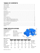
TABLE OF CONTENTS Safety Precautions ………………………………………………………………………………………………… 2 Note to the Owner …………………………………………………………………………………………………. 2 Table of Contents …………………………………………………………………………………………….……. 3 Pump Specifications ……………………………………………………………………………………….……… 3 Introduction ………………………………………………………………………………………………….……… 4 Installation …………………………………………………………………………………………………..……… 5 Pump Setting ……………………………………………………..………………………………………….....…. 6 Initial Start-Up of Pump ……………………………………………….…………………………………….…….
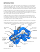
INTRODUCTION The NGP series pump is a positive displacement variable stroke metering pump. It is specifically designed to accurately meter liquid fertilizer solutions. The pump’s construction is of rigid thick walled cast iron cylinders and manifolds for durability and long life. The check valves, piston, and rod are constructed of stainless steel for improved corrosion resistance. Optionally, the pump may be purchased with stainless cylinders and manifolds.
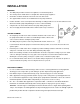
INSTALLATION MOUNTING The NGP pump should be mounted on a rigid base in a horizontal position. The mount position should allow for a straight drive chain and proper tightness. Chain idlers should be installed on the slack side of the drive chain. The supplied rubber washers are installed between the pump and mount. Caution should be exercised on implements with wings or folding members to assure that sufficient area is allowed around the pump and plumbing to not cause contact or binding.
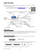
PUMP SETTING The NGP pump output is determined by the drive sprocket ratio and the stroke setting. There are two ways to find the proper setting for your pump: 1. Using the online flow rate calculator at www.cds-johnblue.com .The icon is on the right-hand side of the page, and there is a mobile version available here: 2.
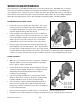
LOADED RADIUS The measurement for the loaded radius must be from the Manufacturer of the tire or be measured under loaded conditions. The loaded radius tire is always the tire that has the first drive sprocket attached to its hub. Ground Wheel Drive Arrangement Measure the loaded radius from the center of the hub to the bottom of the tire where it rests on the ground. Press Wheel Drive Arrangement Measure the loaded radius from the center of the press wheel shaft to where the wheel rests against the tire.
INITIAL PUMP START UP Verify that all installation guidelines have been followed as outlined in the installation section of this manual. Fill the tank full of water to test for leaks in the plumbing system and output of the pump. Fully open the valve at the tank allowing water to fill the suction line and check for leaks. Set the pump to pump setting 10.
MAINTENANCE Check oil daily and fill crankcase to proper level with a quality grade SAE 90 weight gear oil. With the pump sitting level, the oil should be within 1/2” of the bottom of the hole on back of crankcase. You may use a long wire or zip tie as a dipstick to check the level – some length is required due to the hole’s depth. Lubricate all grease zerks on roller chain sprocket spacer, outboard cover plate, crankshaft end, and at stuffing box flange daily.
SERVICE MAINTENANCE Proper maintenance of the NGP pump will ensure a service life for many years. Rebuilding and / or servicing check valves, piston flange packing, piston rod packing, and crankcase components is an economical way to ensure optimum service. This type of service is simple, and can be done by almost all end users. The parts list and schematic section shows the position of all service kit items, which includes all seals, packing, and gaskets.
PISTON ROD PACKINGS The rod packing consists of 2 sets of self-tightening ‘V’ rings which seal around the piston rod to prevent pumped fluid from leaking and protect the crankcase from contamination. Virtually any leakage of the pumped fluid through the vent in the side of the stuffing box is an indication that these rod packing need replacement. However, it is not uncommon for oil to drip form this drain.
CRANKCASE DISASSEMBLY Major pump repair requires some in-depth knowledge on working tolerances for internal parts. We recommend that you contact your nearest CDS-John Blue sales and service dealer for best results in major pump repair. Shaft oil seals have been upgraded from previous L & LM series pumps to include a wiper ring. The oil seals are enclosed in a greaseable cavity to flush debris from around the seal, which is a contributing factor to premature oil seal failure.
INTERNAL DISASSEMBLY Reference to the schematic section is recommended prior to disassembly of the internal crankcase components to familiarize yourself with components. The wet-end components, inboard, and outboard components should be removed prior to internal disassembly as outlined in previous sections of this manual. Supporting the piston rod with a wood block, locate the crosshead pin, which connects the piston rod and connecting rod and carefully drive pin out with a hammer and punch.
PARTS LISTING – NGP- 405x / 605x / 705x Series NGP-4050 NGP-6050 NGP-7050 PART DESCRIPTION KEY SPROCKET RC50-18T PART # L-1020 112661-01 PART # L-1020 112661-01 PART # L-1020 112661-01 55 -K NO SPROCKET NOT USED NOT USED NOT USED 56 -R SPROCKET RC40-18T 113905-01 113905-01 113905-01 3 5/16x3/8 SETSCREW 90532 90532 90532 4 GREASE FITTING H-28 H-28 H-28 5 5/16x3/8 SETSCREW 90532 90532 90532 6 SPROCKET SPACER 115625-01 115625-01 115625-01 7 O-RING S-316 S-316 S-316 8
NGP- 405x / 605x / 705x SERIES 220 FLANGE ADAPTERS: - CAST IRON PUMPS USE 115701-02FLG OR 115601-02FLG - STAINLESS USE 116083-01S SCREWIN ADAPTERS © 2015 CDS-John Blue Co.
PARTS LISTING – NGP- 505x / 805x / 905x SERIES NGP-5050 NGP-8050 NGP-9050 PART DESCRIPTION KEY SPROCKET RC50-18T PART # L-1020 112661-01 PART # L-1020 112661-01 PART # L-1020 112661-01 55 -K NO SPROCKET NOT USED NOT USED NOT USED 56 -R SPROCKET RC40-18T 113905-01 113905-01 113905-01 3 5/16x3/8 SETSCREW 90532 90532 90532 4 GREASE FITTING H-28 H-28 H-28 5 5/16x3/8 SETSCREW 90532 90532 90532 6 SPROCKET SPACER 115625-01 115625-01 115625-01 7 O-RING S-316 S-316 S-316 8
NGP- 505x / 805x / 905x SERIES 220 FLANGE ADAPTERS: - CAST IRON PUMPS USE 115701-02FLG OR 115601-02FLG ON “DR” PUMPS WITHOUT MANIFOLD - STAINLESS AND MANIFOLDS USE 116083-01S SCREWIN ADAPTERS © 2015 CDS-John Blue Co.
PARTS LISTING – DOUBLE ADJUSTABLE PUMPS Parts unique to the NGP-5655-ARF, NGP-8055-AR, and NGP 9055-AR assemblies (refer to the NGP-505x / 805x / 905x chart for common/shared parts) NGP-8050-AR NGP-9050-AR PART DESCRIPTION PART # PART # 1 SPROCKET KEY 106493-01 106493-01 ITEM 15 2 SPROCKET 116055-01 116055-01 3 KEY L-1020 4 SETTING POINTER 115628-01 5 SETTING SCALE L-1002 6 5/16 X 3/8 SET SCREW 90532 7 3/8 X 2-1/4 CAR BOLT 115646-01 8 3/8 SELF LOCKING NUT A-3097 9 ITEM N
NGP Clutch Kit Assembly (optional) Universal Clutch Components - Assemble as shown in the first schematic figure, and ensure that the clutch yoke 21 is installed against the clutch jaw 19 according to the schematic for each assembly (either tight or with a 5/16” gap). - It may be necessary to loosen the set screws on the pump’s stroke adjustment pointer to slide the main shaft over to allow clutch spacer 4 to fit correctly. Be sure to re-tighten the set screws.
Clutch Kit Parts List © 2015 CDS-John Blue Co. -X050 MANUAL -X058 ELEC. -X059 HYD.
Clutch Kit Schematics UNIVERSAL COMPONENTS: (FOR ALL KITS) NGP-x050 MANUAL SHIFT COMPONENTS NGP-x058 ELECTRIC SHIFT COMPONENTS NGP-x059 HYDRAULIC SHIFT COMPONENTS © 2015 CDS-John Blue Co.
DIMENSIONAL FOOTPRINTS © 2015 CDS-John Blue Co.
TROUBLE SHOOTING ISSUE PROBABLE CAUSE Pump hard or impossible to prime Valves damaged or in wrong place Debris lodged in valves Suction line leaks or restriction Pump set too low Packing worn Tank Valve Closed Clogged suction strainer Pump building too much pressure Boom orifices / nozzles wrong size Debris lodged in discharge lines Excessive ground speed Low / Under Metering Valves damaged or in wrong place Debris lodged in valves Suction line leaks or restriction Pump set too low Excessive tire sli
LIMITED WARRANTY THIS WARRANTY IS IN LIEU OF ALL OTHER WRITTEN OR EXPRESS WARRANTIES AND REPRESENTATIONS. ANY IMPLIED WARRANTIES INCLUDING MERCHANTABILITY OR FITNESS FOR ANY PARTICULAR PURPOSE ARE EXPRESSLY LIMITED TO THIS WRITTEN WARRANTY. CDS-JOHN BLUE COMPANY SHALL NOT BE LIABLE FOR CONSEQUENTIAL DAMAGES.