Dual fuel Cooker RV 1200 ..
Dear Customer Thank you for choosing one of our appliances, carefully designed and built by our specialist staff and thoroughly tested to satisfy your cooking requirements. We suggest that you read this Instruction Booklet so that you will understand fully how to operate your appliance. Please keep the booklet handy. You may wish to refer to it at a later date.
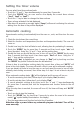
Contents Model RV 1200 .. Page Number Introduction . . . . . . . . . . . . . . . . . . . . . . . . . . . . . . . . . . . . . . . . . . . . . . 4 Features and technical data . . . . . . . . . . . . . . . . . . . . . . . . . . . . . . . . . . . 5 Control panel . . . . . . . . . . . . . . . . . . . . . . . . . . . . . . . . . . . . . . . . . . . . . 6 Clock and timer with “Touch-Control” keys . . . . . . . . . . . . . . . . . . . . . . . . 7 How to use the hob burners . . . . . . . . . . . . . . . . . . . . .
Introduction Congratulations on your purchase of this CDA cooker which has been carefully designed and produced to give you many years of satisfactory use. Before using this appliance it is essential that the following instructions are carefully read and fully understood. We would emphasise that the installation section must be fully complied with for your safety to ensure that you obtain the maximum benefits from your appliance.
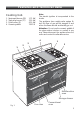
Features and technical data Cooking hob 1. 2. 3. 4. Semi-rapid burner (SR) Triple-ring burner (TC) Dual burner (D) Ceramic griddle 1,75 kW 3,50 kW 4,20 kW 1300 W Note: The electric ignition is incorporated in the knobs. The appliance has a safety valve system fitted, the flow of gas will be stopped if and when the flame should accidentally go out. Attention: Do not use the ceramic griddle if the glass surface is broken or cracked in any way.
Control panel 16 17 1 2 3 15 4 5 6 7 8 14 9 10 11 12 13 Fig. 2 CONTROL PANEL - Controls description 1.Conventional oven thermostat knob (top left oven) 2. Conventional oven switch knob (top left oven) 3.Fan oven thermostat knob (bottom left oven) 4. Fan oven switch knob (bottom left oven) 5. Front left triple-ring burner control knob (2) 6. Rear left semi-rapid burner control knob (1) 7. Central dual burner control knob (3) 8. Ceramic griddle control knob (4) 9.
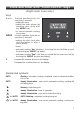
Clock and timer with “Touch-Control” keys (Right main oven only) keys + and – MODE Touched simultaneously (for more than 2 seconds): • setting the clock; • setting the timer volume (by touching once, along with the “MODE” key); • to cancel automatic cooking at any time. Function selection (touched for more than 2 seconds): • setting the clock (only after first connection or after a power failure); • timer; Fig.
“TOUCH-CONTROL” keys The “touch-control” keys shall be operated by the fingers (just by touching the key). When using touch controls it is best to use the ball of your finger rather than the tip. The keys are automatically deactivated: • 8 seconds after the last selection; the deactivation is indicated by an acoustic signal (“beep”). To reactivate just touch the “MODE” key or the “+” and “–” keys (simultaneously) for more than 2 seconds.
Setting the timer volume You can select from three volume levels. • Touch the “+” and “–” keys simultaneously for more than 2 seconds. • Touch the “MODE” key; you can read on the display the current timer volume (“ton1”, “ton2” or “ton3”). • Touch the “–” key to listen or change the timer volume. • Timer volume activated: the last displayed. • After about 8 seconds an acoustic signal (“beep”) will sound confirming the volume setting; then the time of day will be displayed.
How to use the hob burners Gas burners (Semi-rapid and triple ring) Gas flow to the burners is adjusted by turning the knobs (illustrated in fig. 4) which control the valves.
Lighting gas burners fitted with flame failure safety device (Semi-rapid and triple-ring burners) In order to light the burner, you must: 1 – Push and turn the knob in an anticlockwise direction up to the position (maximum rate), push in and hold the knob until the flame has been lit (fig. 4). The sparks produced by the lighter situated inside the relative burner will light the flame.
Gas burners (Dual) The Dual Burner is a very flexible burner which allows different regulations and optimal cooking. It is composed by one inner and two outer crowns; the flame of the inner crown can be regulated separately from the flames of the outer crowns. The Dual Burner can be used: - as a small burner (flame produced only by the inner crown) which can Knob position be adjusted from the maximum ( ) to the minimum ( ) position.
Lighting gas burner fitted with flame failure safety device (Dual Burner) In order to light the burner, you must: 1 – Push and turn the knob in an anticlockwise (fig. 5) direction up to the position (maximum rate of inner and outer crowns); push in and hold the knob until the flame has been lit. The sparks produced by the lighter situated inside the relative burner will light the flame.
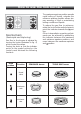
Choice of burner The burner must be chosen according to the diameter of the pans and energy required. Fig. 6 Burners Pan diameter Semi-rapid Triple-ring Dual Wok pans 16 ÷ 24 cm 26 ÷ 28 cm 26 ÷ 28 cm max 36 cm do not use pans with concave or convex bases Saucepans with handles that are excessively heavy in relation to the weight of the pan are less safe as they are more likely to tip. Pans which are positioned centrally on burners are more stable than those which are offset.
Correct use of triple-ring and dual burners The flat-bottomed pans are to be placed directly onto the pan-support. To use the WOK you need to place the proper stand in order to avoid any faulty operation of the triple-ring (figs. 7a - 7b) and dual burner (figs. 8a - 8b). IMPORTANT: The wok pan stand (figs. 7b - 8b) MUST BE PLACED ONLY over the pan-rest for the triple-ring or dual burner. Triple ring burner: WRONG CORRECT Fig. 7a Fig. 7b Dual burner: WRONG CORRECT Fig. 8a Fig.
How to use the ceramic griddle Using the ceramic griddle for the first time The griddle reaches the working temperature very quickly and can grill any food, without fat and oil, directly on the radiant zone's glass-ceramic surface. – Remove the adhesive film which protects some parts. – Remove any residual glue carefully, without using abrasive substances, to avoid scratching the surfaces. – Clean the cooking surface carefully. – Switch the griddle on by turning the power setting knob (fig.
Caution! The griddle becomes very hot during use and remains very hot even after it is switched off. Keep children well out of reach. Tips for grilling: – Preheat the radiant zone sufficiently to obtain quick and uniform cooking. – Do not pour water on the cooking surface when it is switched on or still hot. – If cooking very fatty foods, leave the griddle switched on for a few minutes after cooking is finished, to burn off the fatty residues.
How to use the Multifunction oven (right main oven) Attention: the oven door becomes very hot during operation. Keep children away. General features As its name indicates, this is an oven that presents particular features from an operational point of view. In fact, it is possible to insert 7 different programs to satisfy every cooking need.
Operating principles Heating and cooking in the MULTI-FUNCTION oven are obtained in the following ways: a. by normal convection The heat is produced by the upper and lower heating elements. b. by forced convection A fan sucks in the air contained in the oven muffle, which sends it through the circular heating element and then sends it back through the muffle.
Fig. 10 Fig. 11 Thermostat knob (Fig. 11) This only sets the cooking temperature and does not switch the oven on. Rotate clockwise until the required temperature is reached (from 50 to 250°C). Function selector knob (Fig. 10) Rotate the knob clockwise to set the oven for one of the following functions. Oven light By setting the knob to this position, only the oven light comes on. It remains on in all the cooking modes. Traditional convection cooking The upper and lower heating elements come on.
Grilling The infrared grill element comes on. The heat is dispersed by radiation. Use with the oven door closed and the thermostat knob between 50° and 225°C. For cooking hints, see the chapter “USE OF THE GRILL”. Recommended for: Intense grilling, browning, cooking au gratin and toasting etc. It is recommended that you do not grill for longer than 30 minutes at any one time. Caution: the oven door becomes very hot during operation. Keep children well out of reach.
Ventilated grill cooking The infrared grill element and the fan come on. The heat is dispersed mainly by radiation and the fan then distributes it all over the oven. Use with the door closed. The temperature can be regulated via the thermostat knob to between 50° and 200°C max. The oven must be preheated for approximately 5 minutes. For cooking hints, see the chapter “GRILLING AND AU GRATIN. Recommended for: Grilling where quick browning on the outside is required to keep the juices in.
Cooking advice Sterilization Sterilization of foods to be conserved, in full and hermetically sealed jars, is done in the following way: a. b. c. d. Set the switch to position . Set the thermostat knob to position 185 °C and preheat the oven. Fill the dripping pan with hot water. Set the jars onto the dripping pan making sure they do not touch each other and the door and set the thermostat knob to position 135 °C.
Grilling and “au gratin” Grilling may be done without the roasting jack on position of the switch, because the hot air completely envelops the food that is to be cooked. Set the thermostat to position 200°C maximum and after having preheated the oven, simply place the food on the rack. Close the door and let the oven operate until grilling is done. Adding a few dabs of butter before the end of the cooking time gives the golden “au gratin” effect.
How to use the Fan Oven (bottom left oven) Attention: the oven door becomes very hot during operation. Keep children away. General features With your new Fan oven it is possible to cook a variety of food using the 2 different cooking functions. The 2 positions, thermostatically controlled, are obtained by 2 heating elements.
Operating principles Heating and cooking in the FAN oven are obtained in the following ways: a. by forced convection A fan sucks in the air contained in the oven muffle, which sends it through the circular heating element and then sends it back through the muffle. Before the hot air is sucked back again by the fan to repeat the described cycle, it envelops the food in the oven, provoking a complete and rapid cooking. It is possible to cook several dishes simultaneously. b.
Function selector knob (Fig. 14) Rotate the knob clockwise to set the oven for one of the following functions. Oven light By turning the knob onto this setting we light the oven cavity. The oven remains alight while any of the functions is on. Defrosting frozen foods Only the oven fan is on. To be used with the thermostat knob on “ ” because the other positions have no effect. The defrosting is done by simple ventilation without heat. To rapidly defrost frozen foods; 1 kilogram requires about one hour.
Cooking advice Sterilization Sterilization of foods to be conserved, in full and hermetically sealed jars, is done in the following way: a. b. c. d. Set the switch to position . Set the thermostat knob to position 185 °C and preheat the oven. Fill the dripping pan with hot water. Set the jars onto the dripping pan making sure they do not touch each other and the door and set the thermostat knob to position 135 °C.
Use of the grill Preheat the oven for about 5 minutes. Introduce the food to be cooked, positioning the rack as close to the grill as possible. The dripping pan should be placed under the rack to catch the cooking juices and fats. Grilling with the oven door closed. Do not grill for longer than 30 minutes at any one time. Caution: the oven door becomes very hot during operation. Keep children well out of reach. Oven cooking Before introducing the food, preheat the oven to the desired temperature.
How to use the Conventional Oven (top left oven) Attention: the oven door becomes very hot during operation. Keep children away. General features The conventional oven is equipped with 3 electrical heating elements: – 2 elements (upper and lower) for normal oven cooking – 1 grill element, on the top of the oven, for grilling which must be done with the oven door closed.
Fig. 15 Fig. 16 Operating principles Heating and cooking in the CONVENTIONAL oven are obtained in the following ways: a. by normal convection The heat is produced by the upper and lower heating elements. b. by radiation The heat is radiated by the infra red grill element (use with the oven door closed). Thermostat knob (Fig. 15) This only sets the cooking temperature and does not switch the oven on. Rotate clockwise until the required temperature is reached (from 50°C to 250°C).
Traditional convection cooking The upper and lower heating elements are switched on. The heat is diffused by natural convection and the temperature must be regulated between 50 and 250°C position with the thermostat knob. It is necessary to preheat the oven before introducing the foods to be cooked. Recommended for: For foods which require the same cooking temperature both internally and externally, i. e. roasts, spare ribs, meringue, etc.
Grilling The infra-red heating element is switched on. The heat is diffused by radiation. Use with the oven door closed and the thermostat knob to between 50°C and 200°C. For correct use see chapter “USE OF THE GRILL” Before using the grill, preheat for about five minutes. Always grill with the oven door closed and do not use the grill for longer than 30 minutes at any one time. Caution: The oven door becomes very hot during operation. Keep children well out of reach.
Do’s and do not’s Do’s and do not’s • Do always grill with the oven door closed. • Do read the user instructions carefully before using the cooker for first time. • Do allow the oven to heat for one and a half hours, before using for the first time, in order to expel any smell from the new oven insulation, without the introduction of food. • Do clean your oven regularly. • Do remove spills as soon as they occur. • Do always use oven gloves when removing food shelves and trays from the oven.
Important notes Installation, and any demonstration, information or adjustments are not included in the warranty. The cooker must be installed by a qualified person in accordance with the relevant Standards. In the UK C.O.R.G.I registered installers are authorised to undertake the installation and service work in compliance with the applicable regulations.
Care and maintenance Important: As a safety measure, before you start cleaning the cooker be sure to disconnect it from the mains supply. Do not use a steam cleaner because the moisture can get into the appliance thus make it unsafe. The use of suitable protective clothing/gloves is recommended when handling or cleaning of this appliance. WARNING When correctly installed, your product meets all safety requirements laid down for this type of product category.
Enamelled parts All the enamelled parts must be cleaned with a sponge and soapy water only or other non-abrasive products. Dry preferably with a microfibre or soft cloth. Stainless steel, aluminium, painted parts and silkscreen printed surfaces Clean using an appropriate product. Always dry thoroughly. Stainless steel surfaces: can be cleaned with an appropriate stainless steel cleaner. IMPORTANT: these parts must be cleaned very carefully to avoid scratching and abrasion.
Burners They can be removed and washed with soapy water only. They will remain always perfect if cleaned with products used for silverware. After cleaning or wash, check that burner-caps and burner-heads are dry before placing them in the respective housings. Note: To avoid damage to the electric ignition do not use it when the burners are not in place. Correct replacement of the burners It is very important to check that the burner flame distributor F and the cap C has been correctly positioned (see figs.
Triple ring burner The triple ring burner must be correctly positioned (see fig. 21); the burner rib must be enter in their logement as shown by the arrow see fig. 19). Then position the cap A and the ring B (fig. 20 - 21). The burner correctly positioned must not rotate (fig. 20). T S Fig. 19 A Fig. 20 B Fig.
Correct position of dual burners The DUAL burner must be correctly positioned (see fig. 22); the burner rib must be fitted as shown by the arrows. Position the central small cap in its housing as shown by the arrows (fig. 23). Position the big cap in its housing as shown by the arrows (fig. 24). Fig. 22 IMPORTANT: NEVER unscrew the burner screws (fig. 25). Fig. 23 Fig. 24 Fig.
Inside of ovens Every oven should always be cleaned after use when it has cooled down. The cavity should be cleaned using a mild detergent solution and warm water. Suitable proprietary chemical cleaners may be used after first consulting with the manufacturers recommendations and testing a small sample of the oven cavity. Abrasive cleaning agents or scouring pads/cloths should not be used on the cavity surface.
Assembling and removing the side racks – Assemble the wire racks to the oven walls using the 2 screws (figs. 27a - 27b). – Slide the tray and rack into the runners figs. 28a - 28b. The rack must be fitted so that the safety catch, which stops it sliding out, faces the inside of the oven. – To dismantle, operate in reverse order. TOP LEFT OVEN Fig. 27a Fig. 27b Fig. 28a 42 BOTTOM OVEN RIGHT MAIN OVEN Fig.
Top left and right oven doors Removing the door The oven door can easily be removed as follows: Fig. 29a – Open the door to the full extent (fig. 29a). – Open the lever A completely on the left and right hinges (fig. 29b). A – Hold the door as shown in fig. 29. B – Gently close the door (fig. 29) until left and right hinge levers A are hooked to part B of the door (fig. 29c) Fig. 29b – Withdraw the hinge hooks from their location following arrow C (fig. 29d). – Rest the door on a soft surface.
Top left and right oven doors Cleaning the panes of glass Do not use harsh abrasive cleaners or sharp metal scrapers to clean the oven door glass since they scratch the surface, which may result in shattering of the glass. Fig. 30 A A Removing the inner pane of glass The oven door has two panes. To clean these, you need to remove the inner pane. B 1. Lock the door open: • Fully open the oven door (fig. 30). • Fully open the lever A on the left and right hinges (Fig 31). • Gently close the door (Fig.
Replacing the inner pane of glass 1. Make sure the door is locked open (see figs. 30, 31, 32). D D 2. Replace the inner pane: • Check that the four rubber pads are in place (D in Fig. 35). • Check that you are holding the pane the correct way. You should be able to read the wording on it as it faces you. • Insert the pane in the left E and right F slide guides (fig. 36), and gently slide it to the retainers H (fig. 37).
Bottom left oven door Note: The oven door should only be removed by an authorised service agent. Removal of the oven door by a nonauthorised person will invalidate the guarantee. Fig. 41 Removing the inner pane of glass When removing and replacing the inner glass, the door should be held still by one person (fig. 41). A second person should gently remove the glass (fig. 42). To clean the inner pane of the oven door on both sides operate as follows: • Open the oven door.
Replacing the inner pane of glass To replace the inner pane of the door operate as follows: • Check that the four rubber pads are in place (D in Fig. 43). D • Check that you are holding the pane the correct way. You should be able to read the wording on it as it faces you. • Whilst one person holds the door still, a second person should insert the inner pane in the left E and right F side guides (fig. 44) and gently let it slide up to the retainers H (fig. 45). Fig.
Drawer Removing the drawer (fig. 46) The drawer (fig. 46) comes out like a normal drawer. 1. Open the drawer completely (fig. 46) 2. Move down the lever of left guide (fig. 47) and up the lever of right guide (fig. 48). 3. Remove the drawer; the levers have to be keep moved (fig. 46). Do not store flammable material in the oven or in the drawer. 2 Fig. 48 3 2 Fig. 46 Fig. 47 Fitting the drawer (fig. 49) 1. Insert the drawer guides into the range guides (fig. 49). 2.
FOR THE INSTALLER Location This cooker has class “2/1” overheating protection so that it can be installed next to a cabinet. The appliance may be installed in a kitchen, Kitchen/diner or a bed sitting room, but not in a room or space containing a bath or a shower. The appliance must not be installed in a bed-sitting room of less than 20 m3. The appliance is designed and approved for domestic use only and should not be installed in a commercial, semi commercial or communal environment.
If the cooker is installed adjacent to furniture which is higher than the gas hob cooktop, a gap of at least 200 mm must be left between the side of the cooker and the furniture. Curtains must not be fitted immediatly behind appliance or within 500 mm of the sides. It is essential that the cooker is positioned as stated in Fig. 50. If the cooker is located on a pedestal it is necessary to provide safety measures to prevent falling out.
Before installing the cooker level the appliance by screwing or unscrewing the six adjustable feet fitted below. WARNING! For safety reasons unscrew the feet (from screwed position) to the maximum extent of 5 mm (fig. 51). Fig. 51 Backguard • Assemble the backguard as shown in figure 52 and fix it by the 5 screws A. It is mandatory to install the backguard. A Fig.
Moving the cooker Warning When raising cooker to upright position always ensure two people carry out this manoeuvre to prevent damage to the adjustable feet (fig. 53). Warning Fig. 53 Be carefull: do not lift the cooker by the door handle when raising to the upright position (fig. 54). Warning When moving cooker to its final position DO NOT DRAG (fig. 55). Lift feet clear of floor (fig. 53). Fig. 54 Fig.
Provison for ventilation ✓ The appliance should be installed into a room or space with an air supply in accor- dance with BS 5440-2: 2000. ✓ For rooms with a volume of less than 5 m3 - permanent ventilation of 100 cm2 free area will be required. ✓ For rooms with a volume of between 5 m3 and 10 m3 a permanent ventilation of 50 cm2 free area will be required unless the room has a door which opens directly to the outside air in which case no permanent ventilation is required.
Gas installation IMPORTANT NOTE This appliance is supplied for use on NATURAL GAS or LPG (check the gas regulation label attached on the appliance). ✓ Appliances supplied for use on NATURAL GAS: they are adjusted for this gas only and cannot be used on any other gas (LPG) without modification. The appliances are manufactured for conversion to LPG. ✓ Appliances supplied for use on LPG: they are adjusted for this gas only and cannot be used on any other gas (NATURAL GAS) without modification.
Gas connection The installation of the gas appliance to Natural Gas or LP Gas must be carried out by a C.O.R.G.I. registered installer. Installers shall take due account of the provisions of the relevant British Standards Code of Practice, the Gas Safety Regulations and the Building Standards (Scotland)(Consolidation) Regulations issued by the Scottish Development Department. Installation to Natural Gas Installation to Natural Gas must conform to the Code of Practice, etc.
Gas connection GB Cat: II 2H3+ The gas supply must be connected to the gas inlet which is located at the rear of the appliance (see figure 56). If the connection pipe cross the cooker, it must be positioned under the cooker rear protection. To screw the connecting tube operate with two spanners (fig. 57). After connecting to the mains, check that the coupling are correctly sealed, using soapy solution, but never a flame. Fig. 57 1/2” BSP (male) Fig.
Conversion to Natural Gas or to LPG Injectors replacement of top burners Semi-rapid burner J Every cooker is provided with a set of injectors for the various types of gas. Injectors not supplied can be obtained from the After-Sales Service. Select the injectors to be replaced according to the table at page 59. The nozzle diameters, expressed in hundredths of a millimetre, are marked on the body of each injector.
Adjusting of the minimum of the top burners F In the minimum position the flame must have a length of about 4 mm and must remain lit even with a quick turn from the maximum position to that of minimum. The flame adjustment is done in the following way: Semi-rapid and triple ring burners – – – – Light the burner Set the gas valve to position Remove the knob With a thin screwdriver pass by the hole of microswitch and turn the screw F until adjustment is correct (fig. 61). Fig.
Table for the choice of the injectors GB Cat: G 30 - 28-30 mbar G 31 - 37 mbar G 20 20 mbar Nominal Power Reduced Power [kW] [kW] By-pass [1/100 mm] [1/100 mm] Semi-rapid (SR) 1,75 0,45 32 65 Triple-ring (TR) 3,50 1,50 65 95 0,32 (*) 27 50 (no. 1 central) 1,90 (#) 60 62 (no. 2 outer) inner crown 1,00 (*) Dual (D) outer crown 4,20 (#) Ø injector By-pass [1/100 mm] Ø injector [1/100 mm] 97 (Z) adjustable BURNERS II 2H3+ 135 (T) 69 (F1) (no. 1 central) 95 (Z) (no.
Electrical installation For your safety please read the following information: WARNING! Before effecting any intervention on the electrical parts the appliance must be disconnected from the network. IMPORTANT: The cooker must be installed in accordance with the manufacturer’s instructions. Incorrect installation, for which the manufacturer accepts no responsibility, may cause damage to persons, animals and things.
Electrical feeder cable connection Feeder cable section type H05RRF To connect the feeder cable to the cooker it is necessary to: 230 V – Remove the 6 screws that hold shield A behind the cooker. – Open completely the cable clamp D. – Position the U bolts onto terminal block B (fig. 63) according to the diagram in fig. 64 and fig. 65. – Insert the feeder cable into the cable save P.
Appliance servicing CDA provide a quality and effective after-sales service to cover all your servicing needs. Please attach your receipt to this page for safekeeping. Please help us to help you by having the following information available when booking a service-call: 1. Model type, make and model – see the product data plate. 2. Evidence of installation / purchase date 3. Retailer where appliance was purchased 4. Clear and concise details of the fault 5.
Guarantee CDA appliances carry a five-year parts and a one-year labour guarantee. CDA will repair or replace any defect or part attributable to faulty material or workmanship. Within the first year this will be free of both labour and parts charges. After the first year and within five years, the parts will be supplied free of charge provided that the repair is carried out by an agent authorised by CDA and the labour will be charged at the commercial rate applicable at the time of repair.
Descriptions and illustrations in this booklet are given as simply indicative. The manufacturer reserves the right, considering the characteristics of the models described here, at any time and without notice, to make eventual necessary modifications for their construction or for commercial needs. Cod. 1103158 ß2 RV 1200 ..