
Instructions / Assembly


9. M6 x 20mm Machine Screw (2)
10. M5 x 20mm Machine Screw (2)
11. 8-32 5/8” Machine Screw (2)
12. 1/4”-20 x 1/2” Machine Screw (4)
13. M4 x 8MM Flat Head Machine Screw (2)
14. #8 x 3/4” Self-Tapping Screw (2)
15. #12 x 3/4” Self-Tapping Screw (4)
16. #12 x 1 3/4” Self-Tapping Screw (4)
Instructions for Installing Mounting Plate to Wall or Ceiling:
**For Ceiling Installations, use Speaker Bracket Extension for additional clearance. DO NOT use Speaker Bracket Extension for Wall Installations.**
Page 1 of 2
Instruction / Installation Sheet
Adjustable Speaker Mount
No. 2001
Step 1:
Before beginning the installation process,
test fit your speaker in the desired mounting
location. Make sure that the speaker has
enough clearance from surrounding objects
and walls on all sides by holding your
speaker and the Mounting Plate together in
the desired location and angle.
A
fter clearance has been confirmed in your
desired mounting location, hold the
Mounting Plate to the wall in its correct
position. Using it as a template, mark the
screw hole locations on the mounting
surface with a pen or pencil.
Step 2:
Drill two holes into the mounting surface on the
screw hole locations marked in Step 1. Use
caution to not make the holes too large or the
Plastic Anchor will not have a tight fit.
Type A: Hollow Drywall with No Stud
Use a 5/16” bit.
Type B: Concrete or Brick
Use a 5/16” masonry bit.
Type C: Solid Wood or Wood Stud in Drywall
Use a 1/8” drill bit. For Type C, skip Step 3 and
continue to Step 4.
Step 3:
Insert the plastic anchors by gently
tapping them into the holes with a
hammer until they become flush with the
wall. Be careful to not break or deform the
Plastic Anchor while tapping them in.
Step 4:
Using a Philips head screw driver and two (2) #12
x 1 3/4” Self-Tapping Screws, screw the Mounting
Plate onto the wall.
Step 1
Step 2
Step 3
Step 4
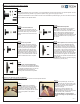
Step 5A: For Wall Installations Only
Insert the Adjustable Link Section onto the
Mounting Plate. Using the Allen Wrench, tighten
the allen screw to secure the Adjustable Link
Section to the Mounting Plate.
Step 5B: For Ceiling Installations Only
Insert the Adjustable Link Section onto the
Speaker Bracket Extension (which was
connected to the Mounting Plate in Step 5).
Using the Allen Wrench, tighten the allen screw
to secure the Adjustable Link Section to the
Speaker Bracket Extension.
Step 5:
For Ceiling Installations Only; for
Wall Installations, skip to Step 5A.
For added clearance with ceiling
installations, connect the Speaker Bracket
Extension to the Mounting Plate. Tighten
the set screw with the Allen Wrench
enough to support the weight of the
speaker. Continue to Step 5B.
Step 5A & 5B
Step 5
Tools Needed:
Philips Screwdriver
Hammer
Stud Finder
Pen or Pencil
Drill
5/16”, 1/8”, 3/32” Drill Bits
*
depending on install method
5/16” Masonry Bit
*
depending on install method
DISTRIBUTED BY HOME DEPOT U.S.
A
., INC.
2455 PACES FERRY RD., N.W.
ATLANTA, GA 30339
WARNING
• Do not install this product without first reading all of the instructions.
• Make sure that the surface you are mounting to is structurally sound.
• Never exceed the maximum speaker weight limit of nine pounds (9 lbs.).
• Tighten screws firmly, but DO NOT over tighten screws.
• CE Tech’s products shall be installed and used only as
indicated in CE Tech’s product instruction sheets.
• For assistance, call 877-527-0313.
Parts Included:
1. Adjustable Link Section (2)
2. Speaker Bracket Extension (2)
3. Speaker Post (2)
4. Mounting Plate (4)
5. 5/32” Allen Wrench (1)
6. M5x1/8” Plastic Washer (2)
7. 8-32 Round Keyhole Nut (2)
8. #12-14 Plastic Anchor (4)