
Datasheet


TECNHICAL CHARACTERISTICS
The T-5 module is an interface with 2 outputs, totally insulated from the opto-coupled input. As a 3 - 24 V DC voltage is
injected on the input, if this one is maintained, the output is activated.
It allows to control thanks to Cmos or TTL signals.
It includes protection against polarity inversion, operating indicator leds and connection terminals.
Din Rail mount Ref C-7584
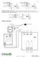
POWER SUPPLY : TheT-5 circuit had to be supplied by a 12 VDC power supply correctly filtered. We recommended you
the FE-2 power supply which has been developed to perfectly answer to the circuit needs. Install a fuse and a switch has it
is indicated on the schedule. Both are necessary for the module’s protection as well as for your own safety, as it is required
by the “CE” regulations. Connect the positive of the power supply to the positive terminal indicated in the wiring map, then
connect the negative of the power supply to the negative terminal indicated in the circuit. Verify that the assembly is
correct.
OPERATING : The T-5 module offer two inputs totally insulated from its corresponding output. Injecting a voltage signal,
included between 3 and 24 V DC, on any input, the relay is activated connecting the corresponding output till the applied
signal decrease at zero.
INSTALLATION : Connect the signal control and module’s inputs signal. Be careful with the polarity and respect positive
and negative terminals.
If the required cable between input connection and its signal source is superior than 30 cm. you have to use shielded cable,
connecting the main wire to the negative terminal of the push button and try to do a cabling inferior than 150 cm.
OUTPUT CONNECTION. LOAD : T-5 outputs are controlled by a relay, and accept any device up to 3 A. The relay
have three output terminals: The normally open quiescent (NO), the normally closed quiescent (NC) and the common. This
mechanism operate like a switch with two terminals NO and Common. For the inverse function.
www.cebek.com - sat@cebek.com
2 OPTO-COUPLED OUTPUT WITH
RELAY – INTERFACE
T-5
Voltage. .....................................................12 V. DC.
Minimum Consumption. ............................ 0.2 mA.
Maximum Consumpiton. ........................... 110 mA.
Minimum Input Voltage. ............................ 3 V. DC.
Maximum Input Voltage. ........................... 24 V. DC.
Maximum Output Load per Relay. ............ 3 A.
Protection against polarity inversion. ........ Yes.
Sizes. ........................................................ 72x64x30mm.