CEBORA S.p.A. 1 SOUND MIG 2035/M Pulse POWER SOURCE art. 285 SERVICE MANUAL 3.302.
CEBORA S.p.A. 2 CONTENTS 1 - GENERAL INFORMATION.......................................................................................................................... 4 - Introduction. ................................................................................................................................................. 4 - General service policy. .................................................................................................................................
CEBORA S.p.A. 3 3.4 - Error codes and alarm signals..................................................................................................................... 28 3.4.1 - 01 - Internal RAM error........................................................................................................................... 28 3.4.2 - 02 - EEPROM error. ................................................................................................................................ 28 3.4.
CEBORA S.p.A. 4 1 - GENERAL INFORMATION 1.1 - Introduction. The purpose of this manual is to train personnel assigned to carry out maintenance on the power source art. 285 for MIG/MAG welding systems. 1.2 - General service policy.
CEBORA S.p.A. 5 2 - SYSTEM DESCRIPTION 2.1 - Introduction. The SOUND MIG 2035/M Pulse is a system for MIG/MAG pulsed synergic, MIG/MAG nonpulsed synergic and MIG/MAG conventional welding. It is made up of an electronic power source (art. 285), and a set of accessories to adapt to various types of applications (see list in Sales Catalogue). The power source is controlled by a microprocessor circuit, which manages the operative functions of the welding system and operator interface.
CEBORA S.p.A. 6 The diode group (56) is made up of two diodes connected to a shared cathode, and provides a positive output voltage with regard to the central socket of the transformer. Actually, each diode in the group is in turn made up of two diodes parallel connected together. The Hall-effect current transducer (33), inserted at the diode group (56) output, sends the feed-back signal of the secondary current to the control board (27) to regulate welding current.
CEBORA S.p.A. 7 2.4 - Programming power source art. 285 (firmware upgrade). The control board (27) contains the main microprocessor of the power source and the memory to set up the parameters of the work programs and synergic curve charts. Programs and synergic curves are defined based on the experience earned by Cebora, and may be upgraded thanks to a programming system that uses the programming board (21) (connector J1) and a RS232 serial communication line.
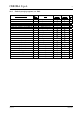
CEBORA S.p.A. 8 2.8 - Programs tables. 2.8.1 - Conventional non synergic programs (ver. H06). Materiale / Material Ferro / Iron Alluminio / Aluminium Acciaio Inox / Stainless Steel ∅filo ∅wire 0,6/0,8/(1) 0,6/0,8/1 0,8/(1) Filo Rame-Silicio3%/CopperSilico3% 2.8.2 0,8/1 Gas Torch Art. 1242 Torch Art. 2003 Prg. N° Argon / 18%CO2 Argon 100% Argon / O2 2% Argon / CO2 2% Argon 100% Argon / He 15% • • • • • • 1 2 3 • • 5 - Conventional synergic programs (ver. H06).
CEBORA S.p.A. 2.8.3 9 - Pulsed synergic programs (ver. P03). ∅filo ∅wire 0,6 0,8 1 Gas Torch Art. 1242 Torch Art. 2003 Prg.
CEBORA S.p.A. 10 2.9 - Set-up mode diagram. OPERATING MODE SET-UP MODE NO WELD OFF switch U=on START-UP O+R long = default O+R O+R dSp O R SP (display G = speed). A (display G = current) (default). O R 2 Spot (led C=on, leds L–M=off). 1 Intermittent (led L=off, leds C–M=on). 0 Continue (led L=on , leds C–M=off ) (default). O R 4 times, automatic. 2 times, manual (default). torch O+R Job torch O+R 2-4 W E L D I N G M O D E torch O+R HSA (default = OF).
CEBORA S.p.A. 11 3 - MAINTENANCE WARNINGS ANY INTERNAL INSPECTIONS OR REPAIRS MUST BE CARRIED OUT BY QUALIFIED PERSONNEL. BEFORE BEGINNING MAINTENANCE OPERATIONS, UNPLUG THE MACHINE FROM THE MAINS AND WAIT FOR THE INTERNAL CAPACITORS TO DISCHARGE (1 MINUTE) 3.1 - Periodic inspection, cleaning. Periodically open the power source grids and check inside the aeration tunnel. Remove any dirt or dust to ensure smooth air flow, and thus adequate cooling of the internal parts of the power source.
CEBORA S.p.A. 3.2.2 12 - Power source operation. NOTE Operations preceded by this symbol refer to operator actions. ♦ Operations preceded by this symbol refer to machine responses that must occur following an operator action. System shut off and disconnected from the mains. Connect the gas intake to the fitting (T) on the rear panel.
CEBORA S.p.A. 13 ♦ Display (G) indicates “dSp” if is the first time you enter in set-up mode, or the function code present last time you exit the set-up mode. ♦ By pressing the torch start button is possible to select all set-up functions available for the program selected, indicated by display Q, during operative mode (see diagram 2.9). Correct? NO (see 3.3.3). YES WARNING DURING THE FOLLOWING TESTS DO NOT AIM THE TORCH AT PEOPLE OR PARTS OF THE BODY, BUT ONLY TOWARDS AN OPEN SPACE OR THE WORKPIECE.
CEBORA S.p.A. 14 3.3 - Troubleshooting. WARNINGS ANY INTERNAL INSPECTIONS OR REPAIRS MUST BE CARRIED OUT BY QUALIFIED PERSONNEL. BEFORE REMOVING THE PROTECTIVE GUARDS AND ACCESSING INTERNAL PARTS, DISCONNECT THE POWER SOURCE FROM THE MAINS AND WAIT FOR THE INTERNAL CAPACITORS TO DISCHARGE (1 MINUTE). NOTE Items in boldface describe problems that may occur on the machine (symptoms). Operations preceded by this symbol refer to situations the operator must determine (causes).
CEBORA S.p.A. 15 ♦ Check the wiring between J3 power supply board (25) and terminals TP3(+) and TP4(-) of power board (26). ♦ With the power source off, temporarily disconnect the power supply board (25) from the power board (26) and check the resistance between terminals 1 and 2 of J3 on power supply board (25). If short-circuited, replace the power supply board (25) and power board (26). ♦ Replace the power board (26). CONTROL BOARD (27) POWER SUPPLY TEST.
CEBORA S.p.A. 3.3.2 16 - Power source powered, control panel on, fan (24) stopped. FAN (24) TEST. Power board (26), connector J2, terminals 1(-) – 2(+) = +27 Vdc. NO Correct? YES ♦ Check the wiring between fan (24) and connector J2 on power board (26). ♦ Make sure that there are no mechanical impediments blocking the fan. ♦ Replace the fan (24). FAN (24) COMMAND TEST. Control board (27), connector J11, terminals 7(+) – 8(-) = +27 Vdc.
CEBORA S.p.A. 3.3.3 17 - Power source powered, display and signals does not indicate the correct values. ERROR CODE TEST. Upon start-up, after the lamp-test, the display (G) flashes and shows an error code. NO Correct? YES ♦ See Error codes and alarm signals, par. 3.4. INDICATOR TEST. Upon start-up, after the lamp-test, display (G) indicates “Hxx” (H = conventional, synergic and non synergic programs tables; xx = the version of the programs (see tables 2.8.1 and 2.8.2)).
CEBORA S.p.A. 3.3.4 18 - The start button produces no effect. TORCH TYPE RECOGNITION TEST. Control board (27), connector J12, terminal 11 (or R85 left side) and connector Jl4 (-) = 0 Vdc with push-pull torch inserted (+5 Vdc with other torches). YES ♦ ♦ ♦ ♦ ♦ ♦ Correct? NO Check the wiring between J12 control board (27) and J1 panel board (41). Make sure the push-pull board (43) is correctly mounted on the panel board (41).
CEBORA S.p.A. 3.3.5 19 - Power source powered, no gas flows from the torch. SOLENOID VALVE (12) TEST. Solenoid valve (12) terminals = 27 Vdc with torch button pressed and as long as the button is held down and the pre-gas and post-gas time set. NO ♦ ♦ ♦ ♦ Correct? YES ♦ Check for gas presence at the power supply fitting (T), and make sure that the pressure and flow in the intake line comply with the values specified for the SOUND MIG 2035/M Pulse.
CEBORA S.p.A. 20 MOTOR SPEED REFERENCE SIGNAL TEST WITH TRADITIONAL TORCH. Control board (27), connector J12 terminal 24 (+) (or C79 left side) and connector J14 (-) = 0 / +5 Vdc adjustable with knob (B). YES ♦ ♦ ♦ ♦ ♦ Correct? NO ♦ Check the wiring between connectors J12 on control board (27) and J1 on panel board (41), and make sure the push-pull board (43) is properly mounted on panel board (41). ♦ Replace the control (27) and/or panel (41) and/or push-pull (43) boards.
CEBORA S.p.A. 21 ♦ Replace the wire feeder motor on the torch, or the entire torch. ♦ Replace the wire feeder motor (401). MOTOR SPEED REFERENCE SIGNAL TEST WITH PUSH-PULL TORCH. Control board (27), connector J12 terminal 4(+) (or C76 right side) and connector J14(-) = approximately 0 Vdc, with UP button on torch pressed; approximately +2.5 Vdc, with DOWN button on torch pressed; +4 Vdc with UP and DOWN buttons released.
CEBORA S.p.A. 3.3.7 22 - In open circuit operation, the output voltage is not regular. OPEN-CIRCUIT OUTPUT VOLTAGE TEST. Power source output terminals (F)(-) and (E)(+) = approximately +62 Vdc, with start button on the torch pressed. NO Correct? YES ♦ Correct operation. WARNING To carry out the following tests you must temporarily disable the output voltage detection circuit, to avoid blockage for “Error 10” (see par. 3.4.3).
CEBORA S.p.A. 23 CURRENT TO PRIMARY CIRCUIT OF TRANSFORMER (30) TEST. Control board (27), connector J4, terminals 3(+) – 4(-) = <0.1 Vdc, current to transformer (30) primary circuit, with start button pressed, and terminals of the secondary circuit disconnected from “anode” terminals of diodes (56). YES Correct? NO ♦ Check the wiring between J4 control board (27) and J6 power board (26).
CEBORA S.p.A. 3.3.8 24 - In resistive load operation, the output voltage is not regular. NOTE For the following tests set continuous “Mode” (led L lit) and the working program n° 1, (see table 2.8.1). Turn the knobs (B) and (I) all the way clockwise (to maximum) and set the other knobs to their central position. OPEN-CIRCUIT OPERATING TEST. Power source output terminal (F)(-) and (E)(+) = approximately +62 Vdc, with start button pressed, without output load.
CEBORA S.p.A. 25 CURRENT ANALOG REFERENCE SIGNAL TEST. Control board (27), connector J12, terminal 23(+) (or C86 left side) and connector J14 (-) = 0 / +5 Vdc adjustable with knob (I). YES Correct? NO ♦ Check the wiring between connectors J12 on control board (27) and J1 on panel board (41), and make sure the push-pull board (43) is properly mounted on panel board (41). ♦ Replace the control (27) and/or panel (41) and/or push-pull (43) boards. CURRENT TRANSDUCER (33) POWER SUPPLY TEST.
CEBORA S.p.A. 26 3.3.9 - Arc difficult to strike, the arc goes out immediately after lighting. “Hot-Start” and “Soft Start” functions are adjustable by set-up menu (see diagram 2.9 and Instruction Manual). Also “Impedance” function, adjustable using knob (P), can assist welding start. Therefore, when dealing with start-up problems and difficulty in maintaining the arc, we recommend: − Checking the “Impedance” function setting by performing the following test.
CEBORA S.p.A. 27 3.3.11 - In synergic mode, the welding quality is not satisfactory, the wire speed is not suited to the output current. NOTE The parameters entered into the synergic programs are drawn from experience, and thus some operators may find themselves working in ideal conditions, while others may need to make slight changes. For this reason the possibility remains to alter, to a small degree, the ratio between wire speed and welding current within the synergic programs.
CEBORA S.p.A. 28 3.4 - Error codes and alarm signals. 3.4.1 - 01 - Internal RAM error. 3.4.2 - 02 - EEPROM error. Block due to software error. Replace the control board (27). 3.4.3 - 10 - Malfunction in the circuit to detect short-circuits at the output. Upon power source start-up this test checks the operating conditions by performing a brief test to generate the open-circuit output voltage. While this is taking place it is important that the torch not touch the workpiece or welding bench.
CEBORA S.p.A. 29 3.4.7 - 30 - Incorrect setting of the minimum current threshold on the control board (27). MINIMUM THRESHOLD CURRENT SETTING. Control board (27), connector J4, terminal 4(-) and test-point TS4(+) = +360 mVdc, with power source powered. YES Correct? NO ♦ Adjust trimmer TR1 on control board (27) to have 360 mVdc +/- 10 mV. ♦ Replace the control board (27). ♦ Correct operation. 3.4.8 - 42 - Error in the signal of the motor encoder (401).
CEBORA S.p.A. 30 Check the wiring between connector J4 of control board (27) and current transducer (33), and the power wiring between the “cathode” terminals of diode group (56) and the central adapter for torch (38), and between the central transformer (30) socket, choke (29) and output terminal (F) of the power source. If you find defective connections, fix and replace any damaged components.
CEBORA S.p.A. 31 − Make sure that the thermostat mounted on the diode group (56) is properly assembled and functioning correctly; its contact must be closed at ambient temperature. − Replace the control board (27). 3.4.16 - 74 - Display (G) indicates tH = igbt high temperature. “tH” on display (G) indicates that power board (26) igbt temperature has risen beyond the allowed limits.
CEBORA S.p.A. 32 4 - COMPONENTS LIST 4.1 - Power source art. 285 : see file ESP285.pdf enclosed at the end of the manual. 4.2 - Components table: see file ESP285.pdf enclosed at the end of the manual. 4.3 - Spare parts list. Essential spare parts. Ref. Code 25 26 27 41 43 56 5602163 5605570 5602157 5602178 5602171 3200200 Description power supply board power board control board panel board push-pull board diode Qty. 1 1 1 1 1 1 Recommended spare parts. Ref.
CEBORA S.p.A. 33 5 - ELECTRICAL DIAGRAMS 5.1 - Power source art. 285 : see file SCHE285.pdf enclosed at the end of the manual. 5.2 - Waveforms. 5.2.1 - Transformer (30) secondary open-circuit voltage (par. 3.3.7). 5.2.2 - PWM1 and PWM2 signals for igbt command on power board (26) (par. 3.3.7). 3.302.
CEBORA S.p.A. 5.2.3 - Wire feeder motor (401) voltage during correct braking (par. 3.3.10). 5.2.4 - Wire feeder motor (401) voltage during incorrect braking (par. 3.3.10). 5.2.5 - Mains voltage present signal (par. 3.4.17). 3.302.
CEBORA S.p.A. 35 5.3 - Filter board (47) code 5.602.164. 5.3.1 - Topographical drawing. 5.3.2 - Connector table. Connector J1 Terminals TP5 - TP6 1-2 Function mains voltage input (230 Vac) mains voltage output (230 Vac). 5.4 - Power supply (25) board code 5.602.163. 5.4.1 - Topographical drawing. 5.4.2 - Connector table. Connector J1 J2 J2 J3 J4 3.302.161 Terminals 1-2 1(+) - 2(-) 3(+) - 4(-) 1(+) - 3(-) - Function 27 Vac output, for igbt temperature detection circuit insulated power supply.
CEBORA S.p.A. 36 5.5 - Power board (26) code 5.602.162. 5.5.1 - Topographical drawing. 5.5.2 - Connector table. Connector J1 J2 J3 J3 J3 J4 J5 J6 J6 J6 J7 J8 J9 - 3.302.161 Terminals 1-2 1(-) - 2(+) 1(+) - 2(-) 3(+) - 4(-) 5(+) - 6(-) 1-2 1-2 1-2 3-4 5-6 1-2 1-2 TP1 - TP2 TP3 - TP4 TP5 - TP6 TRA1 - TRA2 Function 27 Vac input, for igbt temperature detection circuit insulated power supply. fan (24) command output. “mains voltage present” signal output. DC-capacitor pre-charge relay command input.
CEBORA S.p.A. 37 5.6 - Driver-igbt board code 5.600.757. 5.6.1 - Topographical drawing. 5.6.2 - Connector table. Connector J1 J2 J3 J3 J4 J5 Terminals 1-2 1-2 1-2 3-4 1-2 1-2 Function command output for igbt1 gate. command output for igbt2 gate. PWM1 input. PWM2 input. command output for igbt3 gate. command output for igbt4 gate. 5.7 - Control board (27) code 5.602.157. 5.7.1 3.302.161 - Topographical drawing.
CEBORA S.p.A. 5.7.2 - Connector table. Conn. J1 J2 J3 J3 J4 J4 J4 J4 J4 J4 J5 Terminals 1-2 1(+) - 2(-) 3(+) - 1(-) 5-6 1 2 3(+) - 4(-) 5 6(+) - 8(-) 7 1(+) - 9(-) J5 J5 J5 J5 J5 J6 J7 J8 J8 J9 J10 J10 J11 J11 J11 J11 J12 J12 J12 J12 J12 J12 J12 J12 J12 J12 J12 J12 J12 J12 J12 J12 J12 J12 J13 J14 J15 J16 J17 J17 J18 3 5 7 8 10 1-2 3-4 1(+) - 2(-) 3(+) - 4(-) 1-2 3-4 5-6 7-8 1 2 3 4 5 6-7 8 - 9 - 10 11 12 - 13 14-15-16-17 18 19 20 21 22 23 24 25 - 26 1-2 1-4 2 - 3.302.
CEBORA S.p.A. 39 5.8 - Panel board (41) code 5.602.178. 5.8.1 - Topographical drawing. 5.8.2 Conn. J1 J1 J1 J1 J1 J1 J1 J1 J1 J1 J1 J1 J1 J1 J1 J1 J1 J1 J2 J2 J2 J2 J2 J2 J2 J2 J2 - Connector table. Terminals 1 2 3 4 5 6-7 8 - 9 - 10 11 12 - 13 14-15-16-17 18 19 20 21 22 23 24 25 - 26 1-2-3 4 5(-) - 14(+) 6 - 8 - 10 7 - 12 15 - 17 - 19 16 18 20 3.302.161 Function. NU. (spool-gun torch selection output). push-pull motor speed regulator enable input.
CEBORA S.p.A. 40 5.9 - Push-pull board (43) code 5.602.171. 5.9.1 - Topographical drawing. 5.9.2 - Connector table. Conn. J1 J1 J1 J1 J1 J1 J1 J1 J1 J2 J2 J2 J2 J2 J2 J2 J2 J2 Terminals 1 2 3(-) - 10(+) 4(+) - 5(-) 6 7 8 9 10 1-2-3 4 5(-) - 14(+) 6 - 8 - 10 7 - 12 15 - 17 - 19 16 18 20 3.302.161 Function. push-pull torch motor (+) power output. push-pull torch UP/DOWN buttons “cursor” input. +5 Vdc output for push-pull torch UP/DOWN buttons power supply.
CEBORA S.p.A. 5.10 41 - Snubber board (58) code 5.602.166. 5.10.1 - Topographical drawing. 5.10.2 - Connector table. Conn. J1 J3 J4 - Terminals 1-2 1-2 1-2 TP1 - TP5 TP6 - TP10 TP2 - TP7 Function. wire coil cover open signal input. wire coil cover open or diode group (56) overtemperature signals output. diode group (56) overtemperature signal input. transformer (30) secondary circuit end terminal input. transformer (30) secondary circuit end terminal input. diode group (56) cathode terminals output.