
Service manual


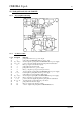

Table Of Contents
- SOUND MIG 2035/M Pulse
- POWER SOURCE art. 285
- filo
- filo
- Gas
- Torch
- Art. 1242
- Torch
- filo
- Gas
- Torch
- Art. 1242
- Torch
- - Set-up mode diagram.
- - MAINTENANCE
- - Periodic inspection, cleaning.
- - Operating sequence.
- - Troubleshooting.
- - The power source does not start, control panel off.
- - Power source powered, control panel on, fan (24) stopped.
- - Power source powered, display and signals does not indicat
- - The start button produces no effect.
- - Power source powered, no gas flows from the torch.
- - Power source powered, the wire feeder motor does not work.
- - In open circuit operation, the output voltage is not regul
- - In resistive load operation, the output voltage is not reg
- - Arc difficult to strike, the arc goes out immediately afte
- - When start button is released, the wire sticks to the work
- - In synergic mode, the welding quality is not satisfactory,
- - Error codes and alarm signals.
- - 01 - Internal RAM error.
- - 02 - EEPROM error.
- - 10 - Malfunction in the circuit to detect short-circuits a
- - 14 - Microprocessor supply voltage error on control board
- - 20 - Absence of interlock signal on power board (26).
- - 25 - Malfunction on the EPLD bus in the control board (27)
- - 30 - Incorrect setting of the minimum current threshold on
- - 42 - Error in the signal of the motor encoder (401).
- - 52 - Start button pressed during start-up.
- - 53 - Start button pressed while resetting from stop due to
- - 54 - Short-circuit between torch and workpiece upon start-
- - 56 - Short-circuit at the output lasts too long (max. allo
- - 60 - Current too high beyond the maximum allowable limits
- - 73 - Display (G) indicates OPn = diode group (56) high tem
- - 80 - Display (G) indicates OPn = wire coil cover open.
- - 74 - Display (G) indicates tH = igbt high temperature.
- - 99 - Display (G) shows OFF = incorrect mains voltage signa
- - COMPONENTS LIST
- - ELECTRICAL DIAGRAMS
- - Power source art. 285 : see file SCHE285.pdf enclosed at t
- - Waveforms.
- - Filter board (47) code 5.602.164.
- - Power supply (25) board code 5.602.163.
- - Power board (26) code 5.602.162.
- - Driver-igbt board code 5.600.757.
- - Control board (27) code 5.602.157.
- - Panel board (41) code 5.602.178.
- - Push-pull board (43) code 5.602.171.
- - Snubber board (58) code 5.602.166.
- - Programming board (21) code 5.602.174.
- - MAINTENANCE
- - Set-up mode diagram.
CEBORA S.p.A. 41
5.10 - Snubber board (58) code 5.602.166.
5.10.1 - Topographical drawing.
5.10.2
- Connector table.
Conn. Terminals Function.
J1 1 - 2 wire coil cover open signal input.
J3 1 - 2 wire coil cover open or diode group (56) overtemperature signals output.
J4 1 - 2 diode group (56) overtemperature signal input.
- TP1 - TP5 transformer (30) secondary circuit end terminal input.
- TP6 - TP10 transformer (30) secondary circuit end terminal input.
- TP2 - TP7 diode group (56) cathode terminals output.
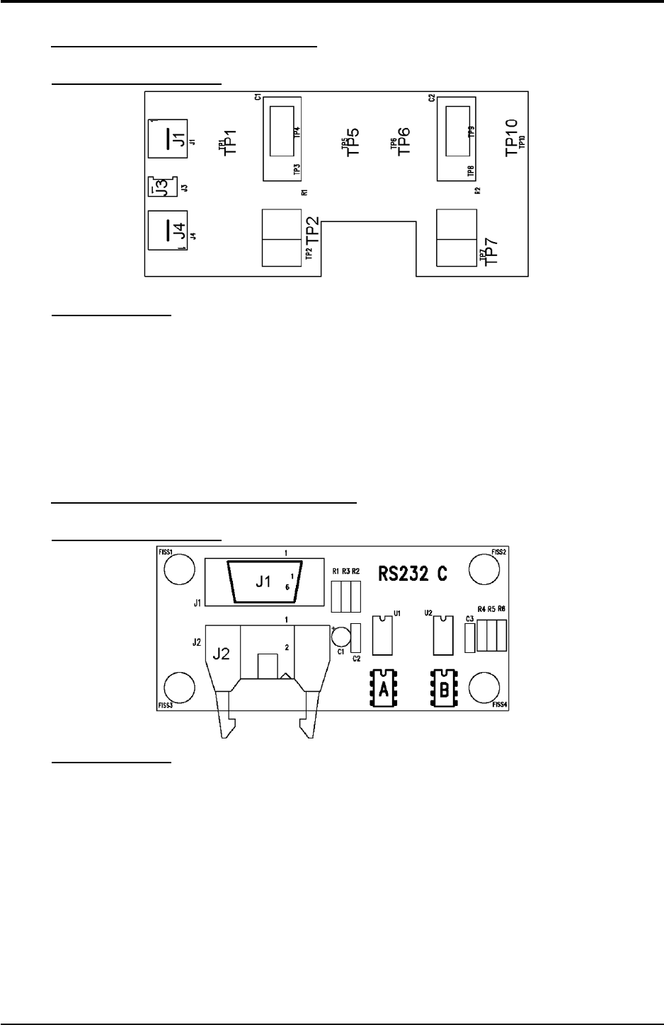
5.11 - Programming board (21) code 5.602.174.
5.11.1 - Topographical drawing.
5.11.2
- Connector table.
Conn. Terminals Function.
J1 2 Tx signal of serial communication line to outside (programming system).
J1 3 Rx signal of serial communication line to outside (programming system).
J1 5 GND for serial communication line signals (programming system).
J1 4 - 6 DTR/DSR signal of serial communication line to outside (programming system).
J1 7 - 8 RTS/CTS signal of serial communication line to outside (programming system)
J2 1(+) - 9(-) +5 Vdc input for programming board (21) and serial communication line to outside power
supply.
J2 3 Tx signal for serial communication line.
J2 5 Rx signal for serial communication line.
J2 7 SDA signal for programming board (21).
J2 8 SCL signal for programming board (21).
J2 10 WP signal for programming board (21).
U1 - connector for custom programs EEPROM.
U2 - connector for custom programs EEPROM.
3.302.161 24/03/2004