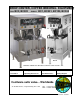
BREW CENTER, COFFEE BREWING EQUIPMENT TWIN: BC2, BC302 SINGLE: BC1, BC301, BC120, BC240 BC-2E BC-1E BREWERS SHOWN WITH OPTIONAL STAINLESS STEEL FUNNEL MANUAL * Specifications * Start up procedure * Adjustments * Parts Identification * Installation * Operating Instructions * Care Maintenance * Wiring Diagram Cecilware sells value...
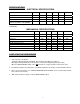
SPECIFICATIONS ELECTRICAL SPECIFICATIONS MODEL NO. Volts Watts BC1 BC301 BC120 BC240 BC2 BC302 120/240 4100 120/240 4100 120 1800 240 3120 120/240 6200 120/240 6280 Amps 18 18 15 13 27 27 Wall Outlet (Receptacle) 6-20R 6-20R 5-15R 6-15R 6-30R 6-30R Power Cord CE202 – 30A optional All Brew Centers are single phase with 3 wires plus a ground with cord and plug, except Eport 220V, 1 PH, (UROPEAN). MECHANICAL SPECIFICATIONS MODEL NO. BC1 BC301 BC120 BC240 BC2 BC302 Tank Capacity (US gal.
INSTALLATION AND OPERATING INSTRUCTIONS Warranty is void if the Brewer is connected to any Voltage other than the Voltage specified on the data label of the Brewer. UNPACKING AND INSPECTION Carefully unpack the Brewer by cutting the straps and lifting the carton off the Brewer.
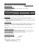
INITIAL PRIMING – Filling of Tank The BC Brewers are shipped with the Thermostat in the OFF position. Do not turn Thermostat to the ON position until the Brewer has been fully primed. a. Turn water supply on and check for leaks at the water inlet connections. Tighten compression fitting if necessary. b. Turn on power to the Brewer. The Brewer will automatically start filling. After 6 minutes the filling cycle will stop and the thermostat should be turned clockwise to the full ON position.
ADJUSTMENTS 1. BY-PASS FLOW VALVE ADJUSTMENTS Depending on the model number, the BC Brewers have been factory set to brew 12, 24 and/or 36 cups of coffee, with the BY-PASS adjusted for a 20% BY-PASS flow of brewing water for the 36 cup, brew output only. Since water hardness, the brand of coffee, and the length of brew time are important factors in final drink taste, it may be necessary to adjust the percentage of BY-PASS.
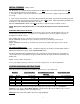
2. TIMER ADJUSTMENT PROCEDURE Remove the top cover to access the brew timer(s). To INCREASE output: turn timer knob a small increment CLOCKWISE. To DECREASE output: turn timer knob a small increment COUNTER-CLOCKWISE. Check output level in carrier. REMOVE JUMPER FOR 240V BCI, BC2 Single Timer (L264A) BC120, BC240 BC301, BC302 Dual Timer (58026) 120 Triple Timer Dual Timer (58027) 240 (Dual Voltage)(L410C) 3. THERMOSTAT ADJUSTMENT The BC Brewers are factory set to deliver hot brewing water at 200' F.
SPECIAL COMPONENTS TEST 1) CHECK DISPENSE VALVES FOR LIME BUILD-UP (Located inside top cabin) Drain the water tank to just below the level of the Dispense Valves. Remove the Valves and clean. You can take these valves apart by hand as shown. Replace the assembly as needed. Replace the valve into the tank and refill tank. 2) WATER INLET VALVE (SOLENOID) TEST (Located inside bottom cabin) Turn power off.
TROUBLESHOOTING GUIDE WARNING: To reduce the risk of electrical shock unplug the dispenser power cord before repairing or replacing any internal components of the unit.. Before any attempt to replace a component be sure to check all electrical connections for proper contact PROBLEM PROBABLE CAUSE REMEDY 1. No power to the machine. a) Loose wire connection. b) Blown fuse. c) Tripped Breaker a) Check wire connections to Power Switch. b) Check fuse. c) Re-set Breaker 2. Machine keeps repeating cycle.
CLEANING AND SANITIZING SANITIZING: All food dispensing units should be sanitized periodically. All parts to be sanitized must be cleaned first. To prepare a sanitizing solution: ADD 2 TSP. OF LIQUID CLOROX BLEACH (5.25% CONCENTRATION) TO 1 GALLON OF WATER AT ROOM TEMPERATURE (70°- 90°F). Note: Always start with a unopened bottle of Clorox Bleach since the solution from an opened bottle has a short life span. • Soak all parts for a minimum of 3 min. in the sanitizing solution.
PARTS IDENTIFICATION [* RECOMMENDED SPARE PARTS] SINGLE UNITS TWIN UNITS BC1, BC301, BC2, BC302 BC120, BC240 ITEM P/N QTY P/N QTY DESCRIPTION 1 SF26A 1 SB49A 1 CABINET TOP COVER 2 -------- SWITCH PANEL LABELS: N829A 1 ---- BC120 & BC240 N892A 1 N815A 1 BC1 / BC2 N822A 1 N823A 1 BC301 / BC302 5* L155A 2 L155A 2 BC2 ON-OFF SWITCH L155A 1 L155A 1 BC120 ON-OFF SWITCH L155A 1 L155A 1 BC240 ON-OFF SWITCH L155A 1 L155A 1 BC1 ON-OFF SWITCH 6* L383A 2 L383A BC120 BREW SWITCHES L383A 1 ….
TOP CABIN OPEN VIEW 1 2 1 3 1 4 1 5 1 6 7 1 1 1 8 1 9 1 TOP CABIN - PARTS IDENTIFICATION [* RECOMMENDED SPARE PARTS] ITEM SPARE SINGLE UNITS TWIN UNITS PARTS P/N QTY P/N QTY 1 2 * * 3 * 4 5 6 7 8* 9 10 11 12 13 14 15 16 17 18 * * * * * * * * * * * * * L656A L499A M532A G367A G369A G286A K683A M483A L688A L689A L264A 58026 L410A B177A SD06Q K671Q M197A E107A K668A M483A M483A M483A L681A K402Q P465A RK70A 1 1 1 1 1 1 1 1 1 1 1 1 1 1 1 1 1 1 1 1 1 1 1 1 L656A L499A M523A G367A G369A G2
BOTTOM CABIN OPEN VIEW 1 5 4 3 2 BOTTOM CABIN - PARTS IDENTIFICATION [* RECOMMENDED SPARE PARTS] BC2-IT BC302-IT SPARE BC301-IT PARTS ITEM 1 2 3 4 5 * * * * P/N QTY P/N L069A B083A CD257 C396A C395A CE202 CG99A 1 1 1 1 1 1 L069A B083A CD257 C396A C395A CE202 CG99A QT Y 1 1 1 1 1 1 12 DESCRIPTION POWER SWITCH TERMINAL BLOCK WATER INLET VALVE FUSE HOLDER FUSE POWER CORD 120/240V or POWER CORD 240V
CARRIER ASS’Y 1 2 3 4 5 6 7 14 CARRIER ASS’Y 97208 Item 1 2 2 3 4 5 6 7 8 9 10 11 12 13 14 [* RECOMMENDED SPARE PARTS] Description Part # * Handle, black 3” 02015 * Hold Down Bracket U833A * Thumb Screw M299A * Carrier Cover S.S.
BC-1E 120/240 3 WIRES + GROUND 3100 WATTS 14A 60Hz REFILL CIRCUIT BREW CIRCUIT PROBE N L1 LOAD L BREW VALVE 1 PH W R B FAUCET & SHANK ASS’Y 99461 BLK HI LIMIT RED BLK GND L1 FUSE 6 AMP. N RED BLACK WHITE D L2 C.G. C.G.
BC120E 2 WIRES+GRD 1800W 15A 1PH BC240E 2 WIRES+GRD 3120W 13A 1PH BREW INDICATOR LIGHT PROBE N L1 LOAD 12 CUP 24 CUP L2 S L1 SW2 SW3 I2 I1 FLOAT SWITCH BLK WARMER HI LIMIT BC-120E DUAL BREWTIME BC-240E DUAL BREWTIME BLK GND L1 FUSE 6 AMP. N RED BLACK WHITE A C.G. C.G.
BC-301E 120/240 3 WIRES+GND 4140W 18A 1PH 60HZ REFILL CIRCUIT BREW CIRCUIT PROBE N L1 LOAD 12 24 36 11 8 INLET VALVE 9 10 BLK HI LIMIT RED BLK BC-301E TRIPLE BREW TIME GND BLK L1 FUSE 6 AMP. N L2 RED BLACK WHITE C C.G. C.G.
BC-2E 120/240 3 WIRE+GRD 6230W 26A 1PH 60HZ PROBE PROBE N L1 LOAD W RB L L W R B BC-2E SINGLE BREW TIME BLK HI LIMIT RED RED BLACK WHITE BLK GND L1 N L2 C C.G. C.G.
9 10 9 10 24 CUP 12 CUP 36 CUP 11 8 36 CUP 12 CUP 24 CUP 36 CUP 12 CUP 24 CUP 24 CUP 12 CUP 36 CUP 11 8 PROBE N L1 LOAD BLK HI LIMIT RED BLACK WHITE RED BLK GND L1 N L2 D C.G. C.G.