CENTURY 2000-IT, COFFEE BREWING EQUIPMENT MODELS C-2003G-IT C-2003RG-IT C-2003LG-IT MANUAL Specifications Installation Operating Instructions Programming Instructions Care Maintenance Adjustments Parts Identification Wiring Diagram Cecilware sells value...
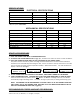
SPECIFICATIONS ELECTRICAL SPECIFICATIONS MODEL NO. C-2003G-IT C-2003RG-IT C-2003LG-IT Volts Watts 120 1,800 120 1,800 120 1,800 Amps Wall Outlet (Receptacle) 15 5-15R 15 5-15R 15 5-15R All Brew Centers are single phase with 2 wires plus a ground with cord and plug, except Eport 220V, 1 PH, 50 cycles (UROPEAN). MECHANICAL SPECIFICATIONS MODEL NO. C-2003G-IT C-2003RG-IT C-2003LG-IT 12 12 12 120 120 120 31 8 17 ¼ 31 16 17 ¼ 31 16 17 ¼ 40 50 50 Tank Capacity (US gal.
FEATURES AND BENEFITS OF THE DIGITAL, MEMBRANE CONTROL TOUCH PAD BREWER 1. 100% Solid State Control for improved reliability. 2. Modular design and reduced component count for ease of service. 3. Optional Low Water Temperature Lockout to prevent dispensing at water temperatures below an adjustable threshold. 4. Redundant system interlocks for uncompromising user safety. 5. Large two line display for viewing system status on digital display and modifying parameters. 6.
INSTALLATION AND OPERATING INSTRUCTIONS Warranty is void if the Brewer is connected to any Voltage other than the Voltage specified on the data label of the Brewer. UNPACKING AND INSPECTION Carefully unpack the Brewer by cutting the straps and lifting the carton off the Brewer.
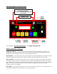
PROGRAMMING INSTRUCTIONS TO ACCESS PROGRAMMING: Press Simultaneously Both Buttons TO SCROLL THRU PROGRAMMING FUNCTIONS: Press One Button TO CHANGE OR RESET PARAMETER VALUES LED LIGHTS D:\1-Milt\Labels & Logos\Techno copy.
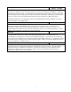
MODES OF OPERATION – DESCRIPTIONS Initialization Mode: The following screen signifies the presence of this mode: CECILWARE &&&&& REV #.# Description – This mode is active only during the first few seconds after “power-on”. The purpose of the Initialization Screen is to identify the System Software Title (depicted by “&&&&&”) and Revision Number (depicted by “#.#”).
BREWING DDD K MM:SS HH:MMP Brewing State Description – This screen is displayed when a Brew Cycle is in progress. The time remaining in the Brew Cycle is displayed in the lower left-hand corner of the screen (depicted as “MM:SS”). The Brew Key LED will blink in this state. The Main Warmer is automatically activated upon entry into this state. The Brewing parameters of Brew Size, Dilution, Pre-Infusion, Pulse Brew, and Drip Time are utilized in this state.
SERVICE MODE Description – The main function of Service Mode is to give qualified personnel the ability to configure the system to meet the requirements of each installation. General Conventions (unless otherwise indicated) 1) 2) 3) 4) 5) 6) To enter or exit Service Mode simultaneously depress both the hidden key under the Cecilware Logo (CW Key) and the hidden key under the first letter of the Model Name (MN Key) until the buzzer sounds (approximately two seconds).
INFUSION TIME - OPTIONAL INFUSION TIME ## SECONDS Description – The Infusion Time is the amount of time that the system will dispense (infuse) hot water into the grinds during the Pre-Infusion process. SOAK TIME – OPTIONAL SOAK TIME ## SECONDS Description – The Soak Time is the amount of time that the system will wait between the end of the hot water infusion period and the beginning of brewing.
WARMER TIMER WARMER TIMER ON/OFF Description – The Warmer Timer feature allows the user to set the maximum length of time a brew remains fresh while being warmed. Once the Warmer Timer has expired an alarm is generated. An alarm consists of a blinking warmer LED and (optionally) the audible alarm (buzzer) sounding. The Warmer Timer is reset (restarted) by cycling the warmer Off and On.
ADJUST SECONDS ADJUST SECONDS DAY HH:MM:## Description – The Adjust Seconds function allows the user to adjust (set) the systems Real-Time-Clock Seconds placeholder. ADJUST MINUTES ADJUST MINUTES DAY HH:##:SS Description – The Adjust Minutes function allows the user to adjust (set) the systems Real-Time-Clock Minutes placeholder. ADJUST HOURS ADJUST HOURS DAY ##:MM:SS Description – The Adjust Hours function allows the user to adjust (set) the systems Real-Time-Clock Hours placeholder.
ERROR MODE Description – The main function of Error Mode is report any system malfunctions and to disable the unit The system must be “powered down” using the Power Key located on the membrane keypad to reset any reported error. KEYPAD ! SYSTEM ERROR ! KEYPAD Description – This screen is displayed and the unit is disabled when a key-press is detected during the initial application of power to the system. This test is not performed during a Power Key initiated “power-on” sequence.
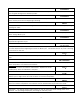
C-2003G-IT FRONT OPEN VIEW 1 18 2 5 4 17 3 16 15 14 13 12 11 6 10 7 8 9 13
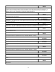
TOP CABIN OPEN VIEW 19 20 32 31 30 21 22 23 24 25 14 26 27 28 29
PARTS IDENTIFICATION FOR C-2003G-IT, C-2003LG-IT, C-2003RG-IT ITEM SPARE PARTS 1 2 3 4 5 6 7 8 9 10 11 12 13 14 15 16 17 18 19 20 21 22 23 24 25 26 27 28 29 30 31 32 * * * * * * * * * * * * * * * * * * * * P/N QTY NG34A L616A L615A P182A K624A P301A M483A R958A L069A C396Q C032A H328Q M042A V001A CD257 M483A RV33Q L573A G356A E105A K668A D042A G095A RV52A + RS33A RV62A RV34Q P465A K402Q L467A M A L683A B203A CH87A L669A H360Q M197A M483A M483A 1 1 1 2 1 2 1 1 1 1 1 1 1 1 1 1 1 1 1 1 1 1 3 1+2 1 1
TROUBLESHOOTING GUIDE WARNING: To reduce the risk of electrical shock unplug the dispenser power cord before repairing or replacing any internal components of the unit.. Before any attempt to replace a component be sure to check all electrical connections for proper contact PROBLEM PROBABLE CAUSE REMEDY a) Loose wire connection. b) Inoperative Power Safety Relay c) Fuse a) Touch Pad defective. b) Inoperative Power Safety Relay. a) Check wire connections to Relay. See Power Safety Relay Test.
SPECIAL COMPONENTS TEST AND ADJUSTMENTS 1) WATER INLET VALVE (SOLENOID) TEST (Located inside bottom cabin) Turn power off from touchpad. If the water level rises inside the tank, and shoots out of the overflow, the Water Inlet Valve is leaking. Disconnect wires from the Water Inlet Valve coil and connect a 2 wire line cord to the terminals. Plug it into a 115V outlet. If water flows in and stops when you pull it out, the Valve is working fine. Repeat this test a few times. The problem may be in the Probe.
5) CHECK DISPENSE VALVES FOR LIME BUILD-UP (Located inside top cabin) Drain The Water Tank To Just Below The Level Of The Dispense Valves. Remove The Valves And Clean. You Can Take These Valves Apart By Hand As Shown. Replace The Assembly As Needed. Replace The Valve Into The Tank And Refill tank. The SINGLE DISPENSE VALVE is factory adjusted to dispense 0.35 oz./sec. of water during the brew cycle (spray duration). TO ADJUST WATER FLOW RATE: Locate adjustment screw on valve (as show here).
HTR DUMP HTR VALVE #1 120VAC 100W HTR #3 100W #2 100W 3 OVERFLOW HOSE THERMISTOR L617A LEVEL PROBE #2 1K1 4 FILL SOLENOID 120VAC 2 4 6 8 10 12 14 16 18 20 22 1 3 5 7 9 11 13 15 17 19 21 + - + + #1 J2 + + + + + + CONTROL BOARD L669A SAFETY RELAY B203A 2 4 6 8 10 12 14 16 18 1 3 5 7 9 11 13 15 17 + + 2+ J1 + + + TEE ASS'Y K681A TANK HEATER G FUSE 6 AMP MT2 MT1 L1 C1 0.