OPERATION MANUAL □ □ □ IC-18A INDUCTION COOKER 120V, 60Hz, 1.8KW IC-22A INDUCTION COOKER 208V, 60Hz, 2.2KW IC-25A INDUCTION COOKER 240V, 60Hz, 2.5KW Cecilware Corporation 43-05 20th Avenue Long Island City, NY 11105 Tel: 800.935.2211, 718.932.1414 Fax: 718.932.7860 Technical Support Tech.Support@cecilware.com Customer Service: Customer.Service@cecilware.com www.cecilware.
USE AND CARE INSTRUCTIONS – IMPORTANT SAFEGUARDS READ ALL INSTRUCTIONS BEFORE OPERATING 1. Use a dedicated electrical circuit. IC-18A: 120V IC-22A: 208V IC-25A: 240V 2. DO NOT block the air-intake panel. Blocking may overheat the unit. 3. Use pans 4.75” (12cm) or larger in diameter. We recommend that pans be less than 10” (26cm) in diameter. Please refer to the next page for a list of suitable and unsuitable pans. 4. DO NOT touch the hot surface of the ceramic plate.
SUITABLE POTS & PANS, - FOR INDUCTION HEATING PLATES 1. Iron 2. Cast iron 3. Stainless steel***** 4. Enamelware *****All pots and pans must have a magnetic bottom.***** All pots and pans must have a flat bottom. All pots and pans should have a diameter between 4.75” (12 cm) and 10.25” (26 cm). UNSUITABLE POTS & PANS, - FOR INDUCTION HEATING PLATES 1. Pot with diameter below 2” (5 cm) 2. Stainless steel pans with aluminum bottom 3. Pottery 4. Glass pans 5. Aluminum pans 6. Bronze pans 7.
HOW DOES YOUR INDUCTION HOB WORK? A high frequency (20-35KHz) induction coil located underneath the ceramic top plate heats the cooking pan by magnetic friction. The heat is produced directly within the pan. It's controlled by an electronic circuit to offer superior performance and functions. During cooking, no energy is lost between the hob and the food. When you switch it off, the cooking is stopped immediately. PRECAUTION BEFORE USING YOUR INDUCTION HOB 1.
Temperature Hold function: By pressing the “Warm” function key, the Temperature Hold function will start working. The LED indicates the temperature will hold at 140°F (+/- 5%), push “Warm” function key again, the LED indicates the temperature will hold at 180°F. When the “Warm” function key is pushed each time, the holding temperature will change as follows: 140°F -> 180°F -> 285°F -> 360°F -> 430°F -> 140°F ->. 7. With the Temperature Hold function working, the “Warm” indicator light will start flashing.
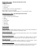
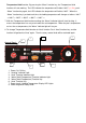
FEATURES & DESCRIPTION: 1 6 9 5 10 7 3 8 2 4 1. Induction Heating Zone 2. Ceramic Top Plate 3. Bottom Chassis 4. Rotary Control Knob (Power Regulator) 5. Induction Heating Indicator Light 6. Heat Function Indicator Light 7. “Warm” Function Indicator Light 8. Air-Intake 9. Air-Outlet 10.
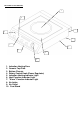
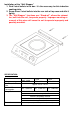
Installation of the “Wall Stopper” 1. Find 2 steel bullets in the box. It’s the accessory for this induction cooking plate. 2. Screw these 2 steel bullets into the rear side of top case and affix it tightly. 3. The “Wall Stopper” functions as a “Stand-off”, allows the exhaust fan, built into the unit, to operate properly. Improper mounting or removal of this piece will cause the unit to operate improperly and possibly overheat. SPECIFICATION: Model No.
TROUBLE SHOOTING 1. If your induction range seems to be working improperly, it doesn't necessarily mean it’s faulty.