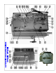
AUTOMATIC GAS WATER BOILER ME10-GN ME15-GN 18 Gauge Type 304L Stainless Steel construction to resist corrosion.
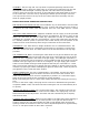
POWER SWITCH GAS FLUE LINE CORD WITH PLUG ME10-GN "B" CAUTION "A" WATER INLET (1/4 " FLARE) HOT SURFACES TEMPERATURE CONTROL GAS INLET (3/8 " NPT) TEMPERATURE CONTROL NP87A OVERFLOW 4.0 SIDE ACCESS DOOR (SLIDES UP) THERMOMETER 14.0 3.4 5.0 16.0 GENERAL SPECIFICATIONS GAS SPECIFICATIONS MODEL NO. NATURAL GAS BTU/ HR @ 3.5" W.C. ME10-GN ME15-GN 12,000 PROPANE GAS BTU/ HR @ 10" W.C.
FOR YOUR SAFETY DO NOT STORE OR USE GASOLINE OR OTHER FLAMMABLE VAPORS AND LIQUIDS IN THE VICINITY OF THIS OR ANY OTHER APPLIANCE. THIS INSTALLATION MUST CONFORM WITH THE NATIONAL FUEL GAS CODE, ANSI Z223.1 (LATEST EDITION). WARNING: IMPROPER INSTALLATION, ADJUSTMENT, ALTERATION, SERVICE OR MAINTENANCE CAN CAUSE PROPERTY DAMAGE, INJURY OR DEATH. READ THE INSTALLATION, OPERATING AND MAINTENANCE INSTRUCTIONS THOROUGHLY BEFORE INSTALLING OR SERVICING THIS EQUIPMENT.
ASSEMBLY: The four legs and vent cap drain are packed separately with the water boiler. Install legs by tilting the water boiler on its side and screwing the legs into the leg supports until hand tight. Carefully right the unit and install in its permanent location, being sure to leave at least 6” on the right side of the water boiler for access to the control box. Level the unit by adjusting the bottom pad of the legs. Place the vent cap into the recess in the top of the unit.
NOTE: On the first lighting it may be necessary to hold the dial for a longer period to allow trapped air to escape from the line. DIAL SETTINGS AND CORRESPONDING WATER TEMPERATURES: “1”= 50F, “10”=198F RELIGHTING: Shut off all gas and wait approximately 5 minutes before relighting the pilot. SHUTTING DOWN: For temporary shut down, turn the thermostat to lowest or OFF position, then turn gas cock dial to PILOT position.
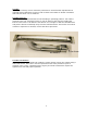
BURNER: The burner is factory set for maximum performance. Should further adjustments be required loosen slotted hex screw on side of venturi and rotate air shutter until flame with soft blue inner core is obtained. BURNER REMOVAL: The burner can be removed with the unit standing in operating position. Turn off the gas flow to the unit. Allow the burner to cool off. Remove the wing nut holding the burner to the frame.
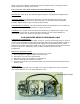
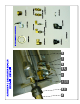
PARTS LIST No.
COMPONENT TESTS - CCW - DECREASES TEMPERATURE A) Thermostat Adjustments: The Thermostat is factory set for proper dispense temperature of 200°F ± 3°F with the control knob set to the maximum clockwise position. If field adjustments are needed proceed as follows: To DECREASE temperature, turn the control knob slightly counter-clockwise.
ELECTRICAL DIAGRAM ME10G-N, ME15G-N 120/ 240 VOLTS N L1 WATER LEVEL CONTROL WATER INLET VALVE RED GND WHT WATER LEVEL PROBES BLU YEL GRN 1 FILL 2 AC-1L 3 AC-2N 4 L-LEVEL 5 H-LEVEL 6 COMMON LED WATER GND POWER LIGHT POWER SWITCH N CECILWARE CORPORATION L1