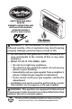
Cedar Ridge ® hearth VENT-FREE GAS WALL HEATER OWNER’S OPERATION AND INSTALLATION MANUAL INFRARED MODELS CH3TPU AND CH4TPU PFS ® US WARNING: If the information in this manual is not followed exactly, a fire or explosion may result causing property damage, personal injury or loss of life. — Do not store or use gasoline or other flammable vapors and liquids in the vicinity of this or any other appliance. — WHAT TO DO IF YOU SMELL GAS • Do not try to light any appliance.
TABLE OF CONTENTS Safety......................................................... 3 Specifications............................................. 4 Qualified Installing Agency......................... 5 Product Features........................................ 5 Local Codes............................................... 5 Preparing For Installation........................... 6 Unpacking.................................................. 6 Water Vapor: A By-Product Of Unvented Room Heaters......................
SAFETY IMPORTANT: Read this owner’s manual carefully and completely before trying to assemble, operate, or service this heater. Improper use of this heater can cause serious injury or death from burns, fire, explosion, electrical shock and carbon monoxide poisoning. NATURAL AND PROPANE/LP GAS: Natural and Propane/LP gas are odorless. An odormaking agent is added to the gas. The odor helps you detect a gas leak. However, the odor added to the gas can fade. Gas may be present even though no odor exists.
SAFETY 1. Do not place Propane/LP supply tank(s) inside any structure. Propane/LP supply tank(s) must be placed outdoors. 2. This heater shall not be installed in a bedroom or bathroom. 3. This heater needs fresh air ventilation to run properly. This heater has an Oxygen Depletion Sensing (ODS) safety shutoff system. The ODS shuts down the heater if not enough fresh air is available. See Air for Combustion and Ventilation, pages 7 through 9. If heater keeps shutting off, see Troubleshooting, page 24. 4.
QUALIFIED INSTALLING AGENCY Only a qualified agency should install and replace gas piping, gas utilization equipment or accessories, and repair and equipment servicing.
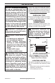
PREPARING FOR INSTALLATION Ignitor Button Control Knob Before beginning assembly or operation of the product, make sure all parts are present. Compare parts with package contents list and Figure 1. If any part is missing or damaged, do not attempt to assemble, install or operate the product. Contact customer service for replacement parts. Grill Front Panel Burner Heater Cabinet Figure 1 - Vent-Free Gas Heater UNPACKING 1. Remove heater from carton. 2.
AIR FOR COMBUSTION AND VENTILATION WARNING: This heater shall not be installed in a confined space or unusually tight construction unless provisions are provided for adequate combustion and ventilation air. Read the following instructions to insure proper fresh air for this and other fuel-burning appliances in your home. Today’s homes are built more energy efficient than ever. New materials, increased insulation and new construction methods help reduce heat loss in homes.
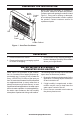
AIR FOR COMBUSTION AND VENTILATION VENTILATION AIR Ventilation Air From Inside Building This fresh air would come from an adjoining unconfined space. When ventilating to an adjoining unconfined space, you must provide two permanent openings: one within 12" of the ceiling and one within 12" of the floor on the wall connecting the two spaces (see options 1 and 2, Figure 2). You can also remove door into adjoining room (see option 3, Figure 2). Follow the National Fuel Gas Code, ANSI Z223.
INSTALLATION NOTICE: This heater is intended for use as supplemental heat. Use this heater along with your primary heating system. Do not install this heater as your primary heat source. If you have a central heating system, you may run system’s circulating blower while using heater. This will help circulate the heat throughout the house. In the event of a power outage, you can use this heater as your primary heat source. WARNING: A qualified service person must install heater. Follow all local codes.
INSTALLATION INSTALLING THERMOSTAT SENSING BULB (OPTIONAL) 1. Pull out the sensing bulb from the two clips located in the shipping position. There is no need to take out the two bulb clips. 2. Take out the bulb clip from the hardware package and insert it into the square hole. Then insert the sensing bulb into the bulb clip (see Figure 5).
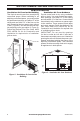
INSTALLATION Attaching Mounting Bracket To Wall Note: Wall anchors, mounting screws, and spacers are in hardware package. The hardware package is provided with heater. Attaching to Wall Stud Method For attaching mounting bracket to wall studs: 1. Drill holes at marked locations using 9/64" drill bit. 2. Place mounting bracket onto wall. Line up last hole on each end of bracket with holes drilled in wall. 3. Insert mounting screws through bracket and into wall studs. 4.
INSTALLATION INSTALLING OPTIONAL BASE FEET (See Accessories, page 30) 1. Snap the left and right foot columns to- 5. Position the heater to the desired location. gether (see Figure 11). Secure the base feet to the floor by using two Phillips head self tapping screws 2. Place the column assembly in the center (provided) (see Figure 13). of the base cut out. Fasten column assembly by using two Phillips head self taping screws (provided) (see Figure 11). 3.
INSTALLATION GAS SELECTION CAUTION: To avoid gas leakage for the gas not being used at the inlet of regulator, a qualified installer or service technician must use supplied cap. You will notice a color coded plunger on the inside of the regulator. This is normal. When the inlet connection fitting is inserted and tightened, this plunger will be pushed back by the fitting making all of the adjustments for the gas being supplied. DO NOT REMOVE THE PLUNGER. The regulator will not work.
INSTALLATION 2. Apply thread sealant to the threads on the connection fitting. While pushing in, rotate the fitting clockwise until the threads engage the regulator. After the fitting has been hand tightened into the regulator use a wrench to complete tightening of the fitting. Install additional fitting to connect to the house supply. FOR NATURAL GAS (NG) INSTALLATION: YELLOW 1. Remove the blue dust cover from the regulator. Blue Dust Cover 2. Remove the metal cap installed over the NG regulator inlet.
INSTALLATION CONNECTING TO GAS SUPPLY WARNING: A qualified service technician must connect heater to gas supply. Follow all local codes. WARNING: This appliance requires a 3/8" NPT (National Pipe Thread) inlet connection to the pressure regulator. WARNING: For natural gas, Never connect heater to private (non-utility) gas wells. This gas is commonly known as wellhead gas. WARNING: Do not overtighten gas connections. CAUTION: Use only new, black iron or steel pipe.
INSTALLATION Typical Inlet Pipe Diameters Use 3/8" black iron pipe or greater. Installation must include an equipment shutoff valve, union, and plugged 1/8" NPT tap. Locate NPT tap within reach for test gauge hook up. NPT tap must be upstream from heater (see Figure 16). IMPORTANT: Install an equipment shutoff valve in an accessible location. The equipment shutoff valve is for turning on or shutting off the gas to the appliance. Apply pipe joint sealant lightly to male threads.
INSTALLATION CHECKING GAS CONNECTIONS WARNING: Test all gas piping and connections for leaks after installing or servicing. Correct all leaks at once. WARNING: Never use an open flame to check for a leak. Apply a noncorrosive leak detection fluid to all joints. If bubbles form, there is a leak. Correct all leaks at once. PRESSURE TESTING GAS SUPPLY PIPING SYSTEM Test Pressures In Excess Of 1/2 PSIG (3.5 kPa) 1.
INSTALLATION PRESSURE TESTING HEATER GAS CONNECTIONS 1. Open equipment shutoff valve (see Figure detection fluid to all joints. Bubbles form18, page 16). ing show a leak. 2. Open gas supply tank valve. 5. Correct all leaks at once. 3. Make sure control knob of heater is in the 6. Light heater (see Lighting Instructions). OFF position. Check all other internal joints for leaks. 4. Check all joints from equipment shutoff 7. Turn off heater (see To Turn Off Gas Appliance, page 20).
6. With control knob pressed in, push down and release ignitor button. This will light pilot. The pilot is attached to the front of burner. The pilot can be seen through the grill. If needed, keep pressing ignitor button until pilot lights. Note: If pilot does not stay lit, refer to Troubleshooting, pages 24 though 27. Also contact a qualified service technician or gas supplier for repairs. Until repairs are made, light pilot with match. To light pilot with match, see Manual Lighting Procedure, page 20. 7.
OPERATION THERMOSTAT CONTROL OPERATION The thermostatic control used on this model differs from standard thermostats. Standard thermostats simply turn the burner on and off. The thermostat used on this heater senses the room temperature. At times the room may ex- ceed the set temperature. If so, the burner will shut off. The burner will cycle back on when room temperature drops below the set temperature. The control knob can be set to any comfort level between HIGH (5) and LOW (1).
ELECTRICAL CONNECTION FOR OPTIONAL BLOWER KIT Do not use this heater if any part of it has been under water. Immediately call a qualified service technician to inspect the heater and replace any part of the electrical system which has been under water. GROUNDING INSTRUCTIONS This heater is for use on 120 volts. The cord has a plug as shown at A in Figure 23. An adapter as shown at C is available for connecting three-blade grounding-type plugs to two-slot receptacles.
INSPECTING BURNERS IMPORTANT: Owner’s should check pilot flame pattern and burner flame pattern often. Incorrect flame patterns indicate the need for cleaning (see Care and Maintenance, page 21) or service. WARNING: Only a qualified service person should service and repair heater. This includes maintenance requiring replacement or alteration of components. PILOT FLAME PATTERN Figure 25 shows a correct pilot flame pattern. Figure 26 shows an incorrect pilot flame pattern.
CARE AND MAINTENANCE WARNING: Turn off heater and let cool before servicing. CAUTION: You must keep control areas, burner, and circulating air passageways of heater clean. Inspect these areas of heater before each use. Have heater inspected yearly by a qualified service technician. Heater may need more frequent cleaning due to excessive lint from carpeting, bedding material, pet hair, etc. WARNING: Failure to keep the primary air opening(s) of the burner(s) clean may result in sooting and property damage.
TROUBLESHOOTING WARNING: If you smell gas: • Shut off gas supply. • Do not try to light any appliance. • Do not touch any electrical switch; do not use any phone in your building. • Immediately call your gas supplier from a neighbor’s phone. Follow the gas supplier’s instructions. • If you cannot reach your gas supplier, call the fire department. WARNING: Only a qualified service technician should service and repair heater. Make sure that power is turned off before proceeding.
TROUBLESHOOTING Problem Possible Cause Corrective Action When ignitor button is 1. Ignitor electrode is posi- 1. Replace electrode. pressed in, there is no tioned wrong. Ignitor elecspark at ODS/pilot. trode is broken. 2. Ignitor electrode is not con- 2. Replace ignitor cable. nected to ignitor cable. 3. Ignitor cable is pinched or 3. Free ignitor cable if pinched wet. by any metal or tubing. Keep ignitor cable dry. 4 Broken ignitor cable. 4. Replace ignitor cable. 5. Bad piezo ignitor. 5.
TROUBLESHOOTING Problem Possible Cause Corrective Action Burner(s) does not light 1. Burner orifice is clogged. after ODS/pilot is lit. 1. Clean burner orifice (see Care and Maintenance, page 23) or replace burner orifice. 2. Burner orifice diameter is too 2. Replace burner orifice. small. 3. Inlet gas pressure is too low. 3. Contact local gas supplier. Delayed ignition of 1. Manifold pressure is too low. 1. Contact local gas supplier. burner(s). 2. Burner orifice is clogged. 2.
TROUBLESHOOTING Problem Possible Cause Corrective Action Heater produces a click- 1. Metal is expanding while 1. This is common with most ing/ticking noise just after heating or contracting while heaters. If noise is excesburner is lit or shut off. cooling. sive, contact qualified service technician. White powder residue 1. When heated, the vapors 1. Turn heater off when using forming within burner from furniture polish, wax, furniture polish, wax, carpet box or on adjacent walls carpet cleaners, etc.
PARTS MODELS CH3TPU AND CH4TPU 9 5 10 6 1 7 2 8 4 5 3 28 www.factorybuysdirect.
PARTS MODELS CH3TPU AND CH4TPU This list contains replaceable parts for your heater. When ordering replacement parts, follow the instructions listed under Replacement Parts on page 30 of this manual.
REPLACEMENT PARTS Note: Use only original replacement parts. This will protect your warranty coverage for parts replaced under warranty. PARTS UNDER WARRANTY Contact authorized dealers of this product. If they can’t supply original replacement parts, call Customer Service toll free at 1-855-607-6557 for referral information.
SERVICE HINTS When Gas Pressure Is Too Low • pilot will not stay lit • burners will have delayed ignition • fireplace will not produce specified heat • propane/LP gas supply might be low (propane/LP units only) You may feel your gas pressure is too low. If so, contact your local gas supplier. TECHNICAL SERVICE You may have further questions about installation, operation, or troubleshooting. If so, contact Factory Buys Direct at 1-855-607-6557.
WARRANTY KEEP THIS WARRANTY Model ________________________________ Serial No. _____________________________ Date Purchased ________________________ Keep receipt for warranty verification. REGISTER YOUR PRODUCT AT WWW.FACTORYBUYSDIRECT.