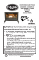
Cedar Ridge ® hearth VENT-FREE GAS STOVE OWNER’S OPERATION AND INSTALLATION MANUAL MODEL CRHQD250TA PFS ® US WARNING: If the information in this manual is not followed exactly, a fire or explosion may result causing property damage, personal injury or loss of life. — Do not store or use gasoline or other flammable vapors and liquids in the v icinity of this or any other appliance. — WHAT TO DO IF YOU SMELL GAS • Do not try to light any appliance.
TABLE OF CONTENTS Safety......................................................... 3 Specifications............................................. 4 Qualified Installing Agency......................... 5 Product Features........................................ 5 Local Codes............................................... 5 Product Identification.................................. 6 Unpacking.................................................. 6 Water Vapor: A By-Product Of Unvented Room Heaters....................
SAFETY IMPORTANT: Read this owner’s manual carefully and completely before trying to assemble, operate, or service this heater. Improper use of this heater can cause serious injury or death from burns, fire, explosion, electrical shock and carbon monoxide poisoning. Failure to follow these instructions will void the warranty. Only a qualified installer, service agent, or local gas supplier may install and service this product.
SAFETY 3. This heater needs fresh air ventilation to run properly. This heater has an Oxygen Depletion Sensing (ODS) safety shutoff system. The ODS shuts down the heater if not enough fresh air is available. See Air for Combustion and Ventilation, pages 7. If heater keeps shutting off, see Troubleshooting, page 22. 4. Keep all air openings in front and bottom of heater clear and free of debris. This will ensure enough air for proper combustion. 5.
QUALIFIED INSTALLING AGENCY Only a qualified agency should install and replace gas piping, gas utilization equipment or accessories, and repair and equipment servicing.
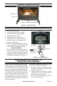
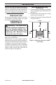
PRODUCT IDENTIFICATION Screen Logs Heater Controls (Inside Panel) Figure 1 - Vent-Free Stove UNPACKING 1. 2. 3. 4. 5. 6. 7. 8. 9. Remove top inner pack. Tilt carton so that heater is upright. Remove protective side packaging. Slide heater out of carton. Remove protective plastic wrap. Hold the screen, lift, and pull forward. Remove log set by cutting plastic ties. Carefully unwrap logs. Check for any shipping damage. If heater or log is damaged, promptly inform your dealer where you bought the heater.
AIR FOR COMBUSTION AND VENTILATION WARNING: This heater shall not be installed in a confined space or unusually tight construction unless provisions are provided for adequate combustion and ventilation air. Read the following instructions to insure proper fresh air for this and other fuel-burning appliances in your home. Today’s homes are built more energy efficient than ever. New materials, increased insulation and new construction methods help reduce heat loss in homes.
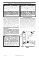
AIR FOR COMBUSTION AND VENTILATION Ventilation Air From Outdoors Provide extra fresh air by using ventilation grills or ducts. You must provide two permaVentilated Outlet Attic nent openings: one within 12" of the ceiling Air and one within 12" of the floor. Connect these items directly to the outdoors or spaces open Outlet Air To Attic to the outdoors. These spaces include attics and crawl spaces. Follow the National Fuel To Gas Code, ANSI Z223.
INSTALLATION IMPORTANT: Vent-free heaters add moisture to the air. Although this is beneficial, installing heater in rooms without enough ventilation air may cause mildew to form too much moisture. See Air for Combustion and Ventilation, pages 7 and 8. CHECK GAS TYPE Be sure your gas supply is right for your heater. Otherwise, call dealer where you bought the heater for proper type heater. Minimum Wall and Ceiling Clearances A.
INSTALLATION GAS SELECTION This appliance is factory preset for propane/LP gas. No changes are required for connecting to propane/LP. Only a qualified installer or service technician can perform gas selection and connecting to gas supply. CAUTION: Two gas line installations at the same time are prohibited. CAUTION: To avoid gas leakage for the gas not being used at the inlet of regulator, a qualified installer or service technician must use supplied cap.
INSTALLATION 2. Apply thread sealant to the threads on a 3/8" NPT brass connection fitting. While pushing in, rotate the fitting clockwise until the threads engage the regulator. After the fitting has been hand tightened into the regulator use a wrench to complete tightening of the fitting. Install additional fitting to connect to the house supply. Fitting supplied by installer, may vary. Use only the cap supplied on the regulator. Do not use an off the shelf pipe plug. This can damage the plunger.
INSTALLATION CONNECTING TO GAS SUPPLY WARNING: A qualified service technician must connect heater to gas supply. Follow all local codes. WARNING: This appliance requires a 3/8" NPT (National Pipe Thread) inlet connection to the pressure regulator. WARNING: For natural gas, Never connect heater to private (non-utility) gas wells. This gas is commonly known as wellhead gas. CAUTION: For propane/LP gas, never connect heater directly to the gas supply. This heater requires an external regulator (not supplied).
INSTALLATION Apply pipe joint sealant lightly to male threads. This will prevent excess sealant from going into pipe. Excess sealant in pipe could result in clogged heater valves. For propane/LP installations, the installer must supply an external regulator. The external regulator will reduce incoming gas pressure. You must reduce incoming gas pressure to between 11" and 14" of w.c. If you do not reduce incoming gas pressure, heater regulator damage could occur.
INSTALLATION CHECKING GAS CONNECTIONS WARNING: Never use an open flame to check for a leak. Apply a noncorrosive leak detection fluid to all joints. If bubbles form, there is a leak. Correct all leaks at once. WARNING: Test all gas piping and connections for leaks after installing or servicing. Correct all leaks at once. PRESSURE TESTING GAS SUPPLY PIPING SYSTEM Test Pressures In Excess Of 1/2 PSIG (3.5 kPa) 1.
INSTALLATION PRESSURE TESTING HEATER GAS CONNECTIONS 1. Open equipment shutoff valve (see Figure 14, page 14). Apply a noncorrosive leak 12, page 14). detection fluid to all joints. Bubbles forming show a leak. 2. Open main gas valve located on or near gas meter for natural gas or open pro- 5. Correct all leaks at once. pane/LP supply tank valve. 6. Light heater (see Lighting Instructions on 3. Make sure control knob of heater is in the page 17). Check all other internal joints OFF position. for leaks. 4.
INSTALLATION INSTALLING LOGS WARNING: Failure to position the parts in accordance with these diagrams or failure to use only parts specifically approved with this heater may result in property damage or personal injury. CAUTION: After installation, and periodically thereafter, check to ensure that no flame comes in contact with any log. With the heater set to high, check to see if flames contact any log. If so, reposition logs according to the log installation instructions in this manual.
OPERATION FOR YOUR SAFETY READ BEFORE LIGHTING WARNING: If you do not follow these instructions exactly, a fire or explosion may result causing property damage, personal injury or loss of life. A. This appliance has a pilot which must be lighted by hand. When lighting the pilot, follow these instructions exactly. B. BEFORE LIGHTING smell all around the appliance area for gas. Be sure to smell next to the floor because some gas is heavier than air and will settle on the floor.
OPERATION Note: If pilot does not stay lit, refer to Troubleshooting, page 22. Also contact a qualified service technician or gas supplier for repairs. Until repairs are made, light pilot with match. To light pilot with match, see Manual Lighting Procedure. 7. Keep control knob pressed in for 30 seconds after lighting pilot. After 30 seconds, release control knob. Note: If pilot goes out, repeat steps 3 through 7. This heater has a safety interlock system. Wait one (1) minute before lighting pilot again. 8.
INSPECTING BURNERS IMPORTANT: Owner’s should check pilot flame pattern and burner flame pattern often. Incorrect flame patterns indicate the need for cleaning (see Care and Maintenance, page 20 or service. WARNING: Only a qualified service person should service and repair heater. This includes maintenance requiring replacement or alteration of components. PILOT FLAME PATTERN Figure 19 shows a correct pilot flame pattern. Figure 20 shows an incorrect pilot flame pattern.
CARE AND MAINTENANCE WARNING: Turn off heater and let cool before servicing. CAUTION: You must keep control areas, burner, and circulating air passageways of heater clean. Inspect these areas of heater before each use. Have heater inspected yearly by a qualified service technician. Heater may need more frequent cleaning due to excessive lint from carpeting, bedding material, pet hair, etc. WARNING: Failure to keep the primary air opening(s) of the burner(s) clean may result in sooting and property damage.
CARE AND MAINTENANCE ODS/PILOT Use a vacuum cleaner, pressurized air, or a small, soft bristled brush to clean. A yellow tip on the pilot flame indicates dust and dirt in the pilot assembly. There is a small pilot air inlet hole about 2" from where the pilot flame comes out of the pilot assembly (see Figure 24). With the unit off, lightly blow air through the air inlet hole. You may blow through a drinking straw if compressed air is not available.
TROUBLESHOOTING WARNING: If you smell gas: • Shut off gas supply. • Do not try to light any appliance. • Do not touch any electrical switch; do not use any phone in your building. • Immediately call your gas supplier from a neighbor’s phone. Follow the gas supplier’s instructions. • If you cannot reach your gas supplier, call the fire department. WARNING: Only a qualified service technician should service and repair heater. Make sure that power is turned off before proceeding.
TROUBLESHOOTING Problem Possible Cause Corrective Action When ignitor button is 1. Ignitor electrode is posi- 1. Replace electrode. pressed in, there is no tioned wrong. Ignitor elecspark at ODS/pilot trode is broken. 2. Ignitor electrode is not con- 2. Replace ignitor cable nected to ignitor cable. 3. Ignitor cable is pinched or 3. Free ignitor cable if pinched wet. by any metal or tubing. Keep ignitor cable dry. 4 Broken ignitor cable. 4. Replace ignitor cable. 5. Bad piezo ignitor. 5.
TROUBLESHOOTING Problem Possible Cause Corrective Action Burner(s) does not light 1. Burner orifice is clogged. after ODS/pilot is lit 1. Clean burner orifice (see Care and Maintenance, page 20). 2. Inlet gas pressure is too low. 2. Contact local gas supplier. Delayed ignition of 1. Manifold pressure is too low. 1. Contact local gas supplier. burner(s). 2. Burner orifice is clogged. 2. Clean burner (see Care and Maintenance, page 20). Burner backfiring during 1. Burner orifice is clogged or 1.
TROUBLESHOOTING Problem Possible Cause Corrective Action White powder residue 1. When heated, the vapors 1. Turn heater off when using forming within burner from furniture polish, wax, furniture polish, wax, carpet box or on adjacent walls carpet cleaners, etc., turn cleaner or similar products. or furniture. into white powder residue. Heater produces un- 1. Heater is burning vapors from 1. Ventilate room. Stop using wanted odors. paint, hair spray, glues, etc.
PARTS MODEL CRHQD250TA 1 2 3 4 15 7 5 11 16 6 8 14 13 12 10 9 26 www.usaprocom.
PARTS MODEL CRHQD250TA This list contains replaceable parts for your heater. When ordering replacement parts, follow the instructions listed under Replacement Parts of this manual.
WARRANTY KEEP THIS WARRANTY Model ________________________________ Serial No. _____________________________ Date Purchased ________________________ Keep receipt for warranty verification. REGISTER YOUR PRODUCT AT WWW.USAPROCOM.COM IMPORTANT: We urge you to register your product within 10 days of date of installation, complete with entire serial number which can be found on the rating plate. Please fill out the warranty information above for your personal records. Retain this manual for future reference.