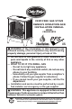
Cedar Ridge ® hearth VENT-FREE GAS STOVE OWNER’S OPERATION AND INSTALLATION MANUAL MODEL CRHSD25RTA PFS ® US WARNING: If the information in this manual is not followed exactly, a fire or explosion may result causing property damage, personal injury or loss of life. — Do not store or use gasoline or other flammable vapors and liquids in the v icinity of this or any other appliance. — WHAT TO DO IF YOU SMELL GAS • Do not try to light any appliance.
TABLE OF CONTENTS Safety......................................................... 3 Qualified Installing Agency......................... 4 Specifications............................................. 5 Product Features........................................ 5 Local Codes............................................... 5 Product Identification.................................. 6 Unpacking.................................................. 6 Water Vapor: A By-Product Of Unvented Room Heaters....................
SAFETY IMPORTANT: Read this owner’s manual carefully and completely before trying to assemble, operate, or service this heater. Improper use of this heater can cause serious injury or death from burns, fire, explosion, electrical shock and carbon monoxide poisoning. Failure to follow these instructions will void the warranty. Only a qualified installer, service agent, or local gas supplier may install and service this product.
SAFETY 1. Do not place Propane/LP supply tank(s) inside any structure. Propane/LP supply tank(s) must be placed outdoors. 2. This heater shall not be installed in a bedroom or bathroom. 3. This heater needs fresh air ventilation to run properly. This heater has an Oxygen Depletion Sensing (ODS) safety shutoff system. The ODS shuts down the heater if not enough fresh air is available. See Air for Combustion and Ventilation, pages 7 and 8. If heater keeps shutting off, see Troubleshooting, page 23. 4.
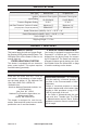
SPECIFICATIONS Model CRHSD25RTA Gas Type Natural Gas Ignition Electronic Piezo Ignitor Input Rating 23,000 Btu/Hr Pressure Regulator Setting Inlet Gas Pressure* (inches of water) (*for purposes of input adjustment) Propane Gas Electronic Piezo Ignitor 23,000 Btu/Hr 4" W.C. 9" W.C. Maximum 9" Maximum 14" Minimum 5" Minimum 11" Heater Dimensions (HxWxD) • 28.31" × 25.75" × 16" Carton Dimensions (HxWxD) • 30.31" × 28.35" × 17.91" Stove Weight • 62.7 lbs Shipping Weight • 71.
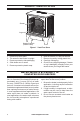
PRODUCT IDENTIFICATION Screen Logs Heater Controls (Inside Panel) Figure 1 - Vent-Free Stove UNPACKING 1. 2. 3. 4. 5. Remove top inner pack. Tilt carton so that heater is upright. Remove protective side packaging. Slide heater out of carton. Remove protective plastic wrap. 6. 7. 8. 9. Hold the screen, lift, and pull forward. Remove log set by cutting plastic ties. Carefully unwrap log. Check for any shipping damage. If heater or log is damaged, promptly inform your dealer where you bought the heater.
AIR FOR COMBUSTION AND VENTILATION WARNING: This heater shall not be installed in a confined space or unusually tight construction unless provisions are provided for adequate combustion and ventilation air. Read the following instructions to insure proper fresh air for this and other fuel-burning appliances in your home. Today’s homes are built more energy efficient than ever. New materials, increased insulation and new construction methods help reduce heat loss in homes.
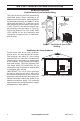
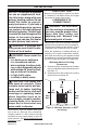
AIR FOR COMBUSTION AND VENTILATION VENTILATION AIR Ventilation Air From Inside Building This fresh air would come from an adjoining unconfined space. When ventilating to an adjoining unconfined space, you must provide two permanent openings: one within 12" of the ceiling and one within 12" of the floor on the wall connecting the two spaces (see options 1 and 2, Figure 2). You can also remove door into adjoining room (see option 3, Figure 2). Follow the National Fuel Gas Code, ANSI Z223.
INSTALLATION NOTICE: This heater is intended for use as supplemental heat. Use this heater along with your primary heating system. Do not install this heater as your primary heat source. If you have a central heating system, you may run system’s circulating blower while using heater. This will help circulate the heat throughout the house. In the event of a power outage, you can use this heater as your primary heat source. WARNING: A qualified service person must install heater. Follow all local codes.
INSTALLATION GAS SELECTION This appliance is factory preset for propane/LP gas. No changes are required for connecting to propane/LP. Only a qualified installer or service technician can perform gas selection and connecting to gas supply. CAUTION: Two gas line installations at the same time are prohibited. CAUTION: To avoid gas leakage for the gas not being used at the inlet of regulator, a qualified installer or service technician must use supplied plug.
INSTALLATION CONNECTING TO GAS SUPPLY WARNING: A qualified service technician must connect heater to gas supply. Follow all local codes. WARNING: This appliance requires a 3/8" NPT (National Pipe Thread) inlet connection to the pressure regulator. WARNING: For natural gas, Never connect heater to private (non-utility) gas wells. This gas is commonly known as wellhead gas. CAUTION: For propane/LP gas, never connect heater directly to the gas supply. This heater requires an external regulator (not supplied).
INSTALLATION Apply pipe joint sealant lightly to male threads. This will prevent excess sealant from going into pipe. Excess sealant in pipe could result in clogged heater valves. For propane/LP installations, the installer must supply an external regulator. The external regulator will reduce incoming gas pressure. You must reduce incoming gas pressure to between 11" and 14" of w.c. If you do not reduce incoming gas pressure, heater regulator damage could occur.
INSTALLATION CHECKING GAS CONNECTIONS WARNING: Test all gas piping and connections for leaks after installing or servicing. Correct all leaks at once. WARNING: Never use an open flame to check for a leak. Apply a noncorrosive leak detection fluid to all joints. If bubbles form, there is a leak. Correct all leaks at once. PRESSURE TESTING GAS SUPPLY PIPING SYSTEM Test Pressures In Excess Of 1/2 PSIG (3.5 kPa) valve located on or near gas meter for 1.
INSTALLATION PRESSURE TESTING HEATER GAS CONNECTIONS 1. Open equipment shutoff valve (see Figure 12, page 13). Apply a noncorrosive leak 10, page 13). detection fluid to all joints. Bubbles forming show a leak. 2. Open main gas valve located on or near gas meter for natural gas or open pro- 5. Correct all leaks at once. pane/LP supply tank valve. 6. Light heater (see Lighting Instructions on 3. Make sure control knob of heater is in the page 17). Check all other internal joints OFF position. for leaks. 4.
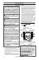
INSTALLATION 4. Place pins on log #4 into holes to the left of the burner as shown in Figure 13, page 14 and Figure 15. 5. Place pins on log #8 into holes to the right of the burner as shown in Figure 13, page 14 and Figure 15. 6. Place pin on log #5 into hole in the left side of log #1 as shown in Figures 15 and 16. Hole for Log #5 Hole for Log #7 Log #8 Log #4 Figure 15 - Logs #4 and #8 7. Place log #6 into cutouts in log #1 and log #2 as shown in Figure 16. 8.
INSTALLATION AA Receiver AA AA AAA Battery Positive UP the receiver and remote. Replace all batteries on a yearly basis or sooner. Position the slide switch on the front of the receiver box in the ON position before installing batteries. Once the batteries are installed you will hear a single beep which indicates the batteries are charged. If you do not hear a beep, replace with new batteries. AA Ignitor Unscrew ignitor cap and install a AAA battery with the + pointing out. Replace cap.
OPERATION LIGHTING INSTRUCTIONS 200125-01A OFF REMOTE 1. STOP! Read the safety information above. 2. Make sure equipment shutoff valve is fully open. 3. Push in control knob slightly and turn clockwise to the OFF position. 4. Wait five (5) minutes to clear out any gas. Then smell for gas around heater and near the floor. If you smell gas, STOP! Follow "B" in the safety information, page 16. If you do not smell gas, go to the next step. 5.
OPERATION 10. If heater will not operate, follow the instructions To Turn Off Gas To Appliance, and call your service technical or gas supplier. CAUTION: Do not try to adjust heating levels by using the equipment shutoff valve. WARNING: If input gas type is NG, make sure NG pilot burner ignites. If input gas type is LP, make sure LP pilot burner ignites. TO TURN OFF GAS TO APPLIANCE Shutting Off Heater Turn control knob clockwise OFF position.
OPERATION Key Settings ON - Operates unit to on position, manually operated solenoid ON. OFF - Operates unit to off position, manually operated solenoid OFF. MODE - Changes unit from manual mode to thermo mode. SET - Sets temperature in thermo mode. TEMP Setting°F/°C Scale The factory setting for temperature is °F. To change this setting to°C, press the ON key and the OFF key on the remote control at the same time (see Figure 21). This will change from°F to °C.
OPERATION THERMOSTAT FUNCTION Setting Desired Room Temperature The remote control system can control the thermostat when the transmitter is in the THERMO mode. The word ROOM must be displayed on the screen. To set the THERMO MODE and desired room temperature: 1. Press the MODE key until the LCD screen shows the word ROOM. The remote is now in the thermostatic mode. 2. Press and hold the SET key until the desired set temperature is reached.
INSPECTING BURNERS IMPORTANT: Owner’s should check pilot flame pattern and burner flame pattern often. Incorrect flame patterns indicate the need for cleaning (see Care and Maintenance, page 22) or service. WARNING: Only a qualified service person should service and repair heater. This includes maintenance requiring replacement or alteration of components. PILOT FLAME PATTERN Figure 25 shows a correct pilot flame pattern. Figure 26 shows an incorrect pilot flame pattern.
CARE AND MAINTENANCE WARNING: Turn off heater and let cool before servicing. CAUTION: You must keep control areas, burner, and circulating air passageways of heater clean. Inspect these areas of heater before each use. Have heater inspected yearly by a qualified service technician. Heater may need more frequent cleaning due to excessive lint from carpeting, bedding material, pet hair, etc. WARNING: Failure to keep the primary air opening(s) of the burner(s) clean may result in sooting and property damage.
CARE AND MAINTENANCE ODS/PILOT Use a vacuum cleaner, pressurized air, or a small, soft bristled brush to clean. A yellow tip on the pilot flame indicates dust and dirt in the pilot assembly. There is a small pilot air inlet hole about 2" from where the pilot flame comes out of the pilot assembly (see Figure 30). With the unit off, lightly blow air through the air inlet hole. You may blow through a drinking straw if compressed air is not available.
TROUBLESHOOTING Using natural gas and pilot will not light. Possible Cause Inlet pressure exceeds 9" WC. Bypass pressure switch. See instructions below. Pressure Switch When using natural gas (NG), there is a pressure switch that acts to turn off the gas flow to the pilot if the inlet pressure exceeds 9.5" WC. This is to prevent the operation of the unit on the wrong gas (propane/LP). If your natural gas supply exceeds 9" WC the unit will not operate.
TROUBLESHOOTING Problem Possible Cause When ignitor button is 1. Gas supply is turned off or pressed in there is a equipment shutoff valve is spark at ODS/pilot but closed. no ignition. 2. C o n t r o l k n o b n o t f u l l y pressed in while pressing ignitor button. 3. Air in gas lines (new installation or recent gas interruption). 4. ODS / pilot is clogged. ODS/pilot lights but flame goes out when control knob is released.
TROUBLESHOOTING Problem Possible Cause High yellow flame during 1. Not enough air. burner combustion. 2. Gas regulator is defective. 3. Inlet gas pressure is too low. Gas odor during com- 1. Foreign matter between bustion. control valve and burner. 2. Gas leak. (See Warning Statement at top of page 23). Slight smoke or odor 1. Residues from manufacturduring initial operation. ing process. Heater produces a whis- 1. Turning control knob to high tling noise when burner position when burner is cold. is lit.
REPLACEMENT PARTS Note: Use only original replacement parts. This will protect your warranty coverage for parts replaced under warranty. PARTS UNDER WARRANTY Contact authorized dealers of this product. If they can’t supply original replacement parts, call Customer Service toll free at 1-866-573-0674 for referral information.
PARTS MODEL CRHSD25RTA 9 6 5 10 10 11 8 11 13 TEMP 7 1 2 4 12 LE AR N ON RE MO TE OF F 3 15-1 14 15-2 OFF PILOT 15-6 ON 15-7 15-8 15-5 15-4 15-3 28 www.usaprocom.
PARTS MODEL CRHSD25RTA This list contains replaceable parts for your heater. When ordering replacement parts, follow the instructions listed under Replacement Parts on page 27 of this manual.
WARRANTY KEEP THIS WARRANTY Model ________________________________ Serial No. _____________________________ Date Purchased ________________________ Keep receipt for warranty verification. REGISTER YOUR PRODUCT AT WWW.USAPROCOM.COM IMPORTANT: We urge you to register your product within 10 days of date of installation, complete with entire serial number which can be found on the rating plate. Please fill out the warranty information above for your personal records. Retain this manual for future reference.
Cedar Ridge ® hearth FOGÓN DE GAS SIN VENTILAS MANUAL DE FUNCIONAMIENTO E INSTALACIÓN DEL PROPIETARIO MODELO CRHSD25RTA PFS ® US ADVERTENCIA: Si la información contenida en este manual no se sigue al pie de la letra, se pueden producir un incendio o una explosión que podrían ocasionar daños a la propiedad, lesiones personales o la pérdida de la vida. — No guarde ni utilice gasolina u otros vapores y líquidos inflamables cerca de este aparato ni de cualquier otro.
TABLE OF CONTENTS Seguridad................................................. 33 Agencia De Instalación Calificada............ 35 Especificaciones....................................... 35 Características Del Producto.................... 36 Normas Locales....................................... 36 Identificación Del Producto....................... 37 Desempaque............................................ 37 Vapor De Agua: Un Producto Derivado de Los Calentadores de Habitación Sin Ventilación..................
SEGURIDAD IMPORTANTE: Lea este manual del propietario cuidadosa y completamente antes de intentar ensamblar, operar o dar servicio a este calentador. El uso inadecuado de este calentador puede causar daños a la propiedad, lesiones graves o la muerte por quemaduras, incendio, explosión, electrocución e intoxicación con monóxido de carbono. No seguir estas instrucciones anula la garantía.
SEGURIDAD ADVERTENCIA: Supervise cuidadosamente a los niños pequeños cuando estén en la habitación en la que se encuentra el calentador. ADVERTENCIA: Debe operar el calentador con la rejilla colocada en su lugar. 1. No ponga los tanques de suministro de gas propano/LP dentro de ninguna estructura. Sitúe los tanques de suministro gas propano/LP en el exterior. 2. Este calentador no debe ser instalado en un dormitorio o un baño. 3.
SEGURIDAD 17. Este calentador de leños está diseñado para no producir humo. Si pareciera que los leños producen humo, apague el calentador y llame a un técnico calificado. Nota: durante el primer uso, es posible que haya un poco de humo debido al curado de los leños y a la combustión de los residuos de fabricación. 18. No haga funcionar el calentador si alguno de los leños está roto.
CARACTERÍSTICAS DEL PRODUCTO PILOTO DE SEGURIDAD El calentador posee un piloto que cuenta con un sistema de apagado de seguridad por medio de un sensor de agotamiento de oxígeno (ODS). El sensor de agotamiento de oxígeno del piloto apaga el calentador si no hay suficiente cantidad de aire fresco. SISTEMA DE ENCENDIDO PIEZOELÉCTRICO 2 OPCIONES DE GAS DISPONIBLES El calentador está diseñado para funcionar con gas propano o con gas natural.
IDENTIFICACIÓN DEL PRODUCTO Rejilla Leños Controles del calentador (En el interior del panel) Figura 1 - Fagón sin Ventilas DESEMPAQUE 1. Retire la parte superior del empaque interno. 2. Incline la caja de manera que el calentador quede en posición vertical. 3. Retire el empaque lateral de protección. 4. Saque el calentador de la caja. 5. Retire el empaque de plástico de protección. 6. Sostenga la malla, levante y tire hacia adelante. 7. Retire el juego de leños cortando los amarres de plástico. 8.
AIRE PARA COMBUSTIÓN Y VENTILACIÓN ADVERTENCIA: Este calentador no se debe instalar en un espacio reducido o excepcionalmente hermético a menos que se tomen las precauciones necesarias para la combustión adecuada y ventilación de aire. Lea las instrucciones siguientes para asegurarse de aire fresco para éste y otros aparatos que queman combustible en su hogar. Las casas de hoy se construyen más energía eficiente que nunca.
AIRE PARA COMBUSTIÓN Y VENTILACIÓN Aire del exterior para ventilación Proporcione aire fresco adicional mediante el uso de rejillas o conductos de ventilación. Debe haber dos aberturas permanentes: una a 30.48 cm (12") del techo y otra a 30.48 cm (12") del suelo. Conecte estos elementos directamente al exterior o a los espacios que estén abiertos al exterior. Estos espacios incluyen áticos y espacios debajo del piso de la casa. Consulte el Código Nacional de Gas Combustible, ANSI Z223.
INSTALACIÓN PRECAUCIÓN: Este calentador crea corrientes de aire caliente. Estas corrientes mueven el calor hacia la superficie de las paredes próximas al calentador. La instalación del calentador cerca de paredes con recubrimientos de vinilo o tela, o la operación del calentador en lugares donde existan impurezas en el aire (como humo de tabaco, velas aromáticas, líquidos limpiadores, lámparas de aceite o de queroseno, entre otros), puede manchar las paredes o producir olores.
INSTALACIÓN PRECAUCIÓN: Para evitar la fuga de gas para el gas no se utiliza en la entrada del regulador, un instalador o técnico de servicio calificado debe utilizar el enchufe suministrado. ADVERTENCIA: No intente acceder o cambiar la configuración de los medios de selección de combustible.
INSTALACIÓN CONEXIÓN AL SUMINISTRO DE GAS ADVERTENCIA: Una persona de servicio capacitada debe conectar el calentador al suministro de gas. Siga todas las normas locales. ADVERTENCIA: Este aparato requiere una conexión de entrada tipo NPT (rosca de tubería nacional) de 3/8" al regulador de presión. ADVERTENCIA: Para gas natural, nunca conecte el calentador a pozos de gas privados (que no sean de servicio público). Este gas se conoce comúnmente como gas de pozo.
INSTALACIÓN Antes de instalar el calentador, asegúrese de tener los elementos que se indican a continuación.
INSTALACIÓN El instalador debe proveer un regulador externo. El regulador externo reducirá la presión del gas entrante. Debe reducir la presión del gas entrante de manera que esté entre 11" y 14" de c.a. Si no reduce la presión del gas entrante, se pueden producir daños al regulador del calentador. Instale el regulador externo con la ventila apuntando hacia abajo. Como se muestra en la figura 9, pagina 43. El apuntar la ventila hacia abajo la protege de la lluvia helada o aguanieve.
INSTALACIÓN Presiones de prueba iguales o menores a 3.5 kPa (1/2 PSI) 1. Cierre la válvula de cierre del equipo Tanque de Válvula de cierre del equipo suministro de (consulte la figura 10). 2. Regule la presión del sistema de tubería gas propano/ de suministro ya sea abriendo la válvula LP del tanque de suministro de gas propano/ LP, en caso que utilice este tipo de gas, o bien, abriendo la válvula principal de gas que se localiza en el medidor de gas natural o cerca de éste, o bien, usando aire comprimido.
INSTALACIÓN INSTALACIÓN DE LOS LEÑOS ADVERTENCIA: Si no coloca las piezas de acuerdo con estos diagramas o no usa piezas aprobadas específicamente para este calentador pueden producirse daños a la propiedad o lesiones personales. PRECAUCIÓN: Después de la instalación y en lo sucesivo, compruebe periódicamente que ninguna llama esté en contacto con algún leño. Ponga el calentador en HI (alto) y observe si las llamas tocan los leños.
INSTALACIÓN 8. Coloque las clavijas del leño #7 en el orificio en el lado derecho del leño # 1 como se muestra en las Figuras 15 y 16. IMPORTANTE: Asegúrese de que los leños no cubren los orificios del quemador. Es muy Orificios para leño #5 Orificios para leño #7 Leño #8 Leño #4 Figura 15 - Leños #4 y #8 importante instalar los leños exactamente como se indica en las instrucciones. No modifique los leños. Utilice sólo los leños suministrados con el calentador.
INSTALACIÓN AA AA AA Batería AAA AAA Battery polo Positive positivo UP hacia arriba causar daños en el receptor y el mando a distancia. Reemplace todas las pilas una vez al año o antes. Coloque el interruptor deslizante en la parte frontal de la caja del receptor en la posición ON antes de instalar las baterías. Una vez instaladas las baterías se oye un pitido que indica que las baterías están cargadas. Si no se oye un pitido, vuelva a colocar unas nuevas.
FUNCIONAMIENTO INSTRUCCIONES DE ENCENDIDO 200125-01A OFF REMOTE 1. ¡ALTO! Lea la información de seguridad. 2. Asegúrese de que la válvula de cierre del equipo esté completamente abierta. 3. Presione levemente la perilla de control y gírela en dirección de las manecillas del reloj hasta la posición OFF. 4. Espere cinco (5) minutos a que se disipe el gas. Luego acérquese para ver si percibe olor a gas, incluso cerca del suelo.
FUNCIONAMIENTO 9. Gire la perilla de control en sentido contrario al de las manecillas del reloj a la posición de encendido. El quemador principal deberá encenderse. Nota: Si el quemador no se enciende, presione el interruptor deslizante de la caja del receptor a la posición OFF y luego nuevamente a la posición ON. Nota: Espere un minuto después de apagar el calentador para permitir que la válvula de control se restablezca antes de encender nuevamente la unidad. 10.
FUNCIONAMIENTO Nota: Remote debe ser de al menos 5 metros de distancia del receptor durante el proceso de aprendizaje. Nota: Si el control remoto se pierde o se daña, el interruptor deslizante del receptor puede ser utilizado para hacer funcionar el calentador. Nota: Cuando las pilas se sustituyen el proceso de aprendizaje, deberán repetirse. CONFIGURACION ON - Opera la unidad en la posición de encendido, solenoide operado manualmente en ON.
FUNCIONAMIENTO FUNCIONAMIENTO DE APAGADO Presione la tecla OFF y se apagará la llama del artefacto. Durante este tiempo la pantalla LCD mostrará la palabra OF (consulte Figura 24). Después de 3 segundos, la pantalla LCD mostrará en forma predeterminada la temperatura TEMP con la palabra TEMP (consulte Figura 24).
INSPECCIÓN DE LOS QUEMADORES IMPORTANTE: El propietario debe revisar frecuentemente los patrones de la llama del piloto y de la llama del quemador. Patrones de llama incorrectos indican la necesidad de limpieza o servicio de mantenimiento (consulte Cuidado y mantenimiento, página 54). ADVERTENCIA: Sólo una persona de servicio capacitada debe repararlo o darle servicio. Esto incluye el mantenimiento requerido, refacciones o alteración de componentes.
CUIDADO Y MANTENIMIENTO ADVERTENCIA: Apague el calentador y deje que se enfríe antes de darle mantenimiento. Sólo una persona de servicio capacitada debe repararlo o darle servicio. PRECAUCIÓN: Debe mantener limpias las áreas de control, el quemador y las vias de circulación de aire del calentador. Inspeccione estas áreas del calentador antes de cada uso. Haga que una persona de servicio calificada inspeccione el calentador una vez al año.
CUIDADO Y MANTENIMIENTO ODS/PILOTO Utilice una aspiradora, aire comprimido o un cepillo pequeño, de cerdas suaves para limpiarlos. Si la llama del piloto tiene la punta amarilla, indica la presencia de polvo y suciedad en el ensamble del piloto. Hay un pequeño orificio de entrada de aire al piloto, aproximadamente de 5 cm (2") de diámetro de donde sale la llama del piloto (consulte la figura 30). Con la unidad apagada, haga pasar aire ligeramente a través del orificio de entrada de aire.
SOLUCIÓN DE PROBLEMAS IMPORTANTE: Si hace funcionar el calentador donde existen impurezas en el aire se pueden producir olores. Los productos de limpieza, pintura, solventes de pintura, humo de cigarro, cementos y pegamentos, alfombras o textiles nuevos, etc., producen gases. Estos gases se pueden mezclar con el aire que se utiliza para la combustión y producir olores. Nota: todos los puntos para solución de problemas se listan en orden de funcionamiento.
SOLUCIÓN DE PROBLEMAS Problema Causa Posible Acción Correctiva Cuando se presiona el 1. Electrodo de encendido está 1. Remplace el electrodo del mal colocado. Electrodo de encendedor. botón del encendedor, no encendido está roto. hay chispa en el piloto/ ODS. 2. El electrodo del encendedor 2. Remplace el cable del enno está conectado al cable cendedor. del encendedor. 3. El cable del encendedor está 3. Libere el cable del encencomprimido o mojado. dedor si algún metal o tubería lo está comprimiendo.
SOLUCIÓN DE PROBLEMAS Problema Causa Posible Acción Correctiva El piloto/ODS se en- 1. La perilla de control no está 1. Presione la perilla de control ciende, pero la llama se presionada completamente. completamente. extingue cuando la perilla 2. La perilla de control no se 2. Después de que el piloto/ de control se suelta presionó durante el tiempo ODS se encienda, mantenga suficiente. la perilla de control presionada durante 30 segundos. 3. La válvula de cierre del 3.
SOLUCIÓN DE PROBLEMAS Problema Causa Posible Acción Correctiva Llamas amarillas alta 1. No hay suficiente aire. durante la combustión en el quemador. 1. Revise el quemador en busca de polvo y residuos. Si los hay, limpie el quemador (consulte Cuidado y mantenimiento, en la página 54). 2. El regulador de gas está 2. Remplace el regulador de defectuoso. gas. 3. La entrada de la presión de 3. Contacte a su proveedor gas es demasiado baja. local de gas. Hay olor a gas durante la 1.
SOLUCIÓN DE PROBLEMAS Problema Causa Posible Acción Correctiva El calentador produce 1. En el calentador se están 1. Abra la ventana para ventilar quemado vapores provela habitación. Deje de utilizar olores no deseados. nientes de pintura, fijador los productos que ocasionan para el cabello, pegamentos, el olor mientras el calentador productos de limpieza, proesté funcionando. ductos químicos, alfombras nuevas, etc. (Consulte la nota IMPORTANTE pagina 55). 2. Fugas de gas. Consulte la 2.
PIEZAS DE REPUESTO Nota: use sólo piezas de repuesto originales. Esto protegerá la cobertura de su garantía para partes remplazadas bajo la garantía. PIEZAS CON Comuníquese con los distribuidores autorizados de este producto. Si no pueden proporcionarle las piezas originales de repuesto, llame gratis al Departamento de Servicio al Cliente al 1-866-573-0674 para obtener información de referencia.
PIEZAS MODELOS CRHSD25RTA 9 6 5 10 10 11 8 11 13 TEMP 7 1 2 4 12 LE AR N ON RE MO TE OF F 3 15-1 14 15-2 OFF PILOT 15-6 ON 15-7 15-8 15-5 15-4 15-3 62 www.usaprocom.
PIEZAS MODELO CRHSD25RTA Esta lista contiene las piezas remplazables utilizadas en el calentador. Al hacer un pedido de piezas, siga las instrucciones listadas en Piezas de repuesto en la página 61 de este manual. Artículo Pieza # Descripción Cant.
GARANTÍA GUARDE ESTA GARANTÍA Modelo___________________________________ Número de serie___________________________ Fecha de compra __________________________ Conserve su recibo para la verificación de la garantía. REGISTRE SU PRODUCTO EN WWW.USAPROCOM.COM IMPORTANTE: Le pedimos que registre su producto dentro de los 10 días de la fecha de instalación, lleve a cabo con el número de serie completa que se puede encontrar en la placa de características.