CeilAiR OHS Series Installation, Operation & Maintenance Manual (Mar, 2012) Air Technology Systems, Inc.
CeilAiR OHS Series Installation, Operation & Maintenance Manual MODEL NOMENCLATURE OHS-040-G-FC AWS = Alternate Water Source OHS = Overhead System FC = Free Cooling LP = Low Profile Configuration SF = Same-Face Air Pattern SP = Special Configuration AHU = Air Handling Unit Nominal Capacity in 1,000’s of BTU/Hr AR = Air-Cooled Remote (Split) AS = Air-Cooled Self-Contained C = Chilled Water System CAA = Indoor Centrifugal Condenser D( ) = Dual (Two) Circuit System G = Glycol-Cooled H( )
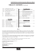
CeilAiR OHS Series Installation, Operation & Maintenance Manual TABLE OF CONTENTS 1.0 1.1 1.2 1.3 1.4 1.5 1.5.1 1.5.2 1.6. Introduction ............................................1-1 General.....................................................1-1 Product Description ..................................1-1 Controls ....................................................1-2 Product Warranty .....................................1-3 Safety .......................................................1-4 General........
CeilAiR OHS Series Installation, Operation & Maintenance Manual TABLE OF CONTENTS (Continued) 4.3.4.2 4.3.4.3 4.3.4.4 4.3.4.5 Standard Cleanout Procedure ..................4-7 Burn-Out/Acidic Cleanup Procedure ........4-7 Humidifier Cylinder Replacement .............4-7 Filter Replacement ...................................4-8 5.0 5.1 5.2 5.3 Product Support .....................................5-1 Technical Support .....................................5-1 Obtaining Warranty Parts ......................
CeilAiR OHS Series Installation, Operation & Maintenance Manual 1.0 Introduction 1.1 General Thank you for your selection of the CeilAiR® ceilingmounted air conditioning system made by Stulz Air Technology Systems, Inc. CeilAiR overhead air conditioning systems (OHS) are designed and constructed using the finest available materials/components, state-of-the-art technology and quality craftsmanship to provide years of troublefree service.
CeilAiR OHS Series Installation, Operation & Maintenance Manual 1.4 Product Warranty STULZ AIR TECHNOLOGY SYSTEMS, INC. 12 MONTH PRECISION A/C LIMITED WARRANTY / 24 MONTHS PRECISION A/C UPGRADED LIMITED WARRANTY The 12 month Precision A/C Limited Warranty applies when the Product Support Network Factory Start-Up is not purchased at the time of order entry.
CeilAiR OHS Series Installation, Operation & Maintenance Manual SATS offers a two year standard limited warranty as stated on the previous page. Additionally an extended warranty may be purchased on the unit’s compressor. The compressor warranty as stated below will be sent with your unit if the option is purchased and should be retained for future reference. You may consult the factory to verify if the extended compressor warranty was purchased for your system. STULZ AIR TECHNOLOGY SYSTEMS, INC.
CeilAiR OHS Series Installation, Operation & Maintenance Manual 1.5 Safety WARNING 1.5.1 General Stulz Air Technology Systems, Inc. uses notes along with caution and warning symbols throughout this manual to draw your attention to important operational and safety information. To prevent personal injury, stay clear of rotating components as automatic controls may start them unexpectedly. Turn off power to the unit unless you are performing tests that require power.
CeilAiR OHS Series Installation, Operation & Maintenance Manual CAUTION WARNING This unit employs high voltage equipment with rotating components. Exercise extreme care to avoid accidents and ensure proper operation. WARNING When working on electrical equipment, remove all jewelry, watches, rings, etc. WARNING Refrigerant (R407C or R410A) is used with this equipment. Death or serious injury may result if personnel fail to observe proper safety precautions.
CeilAiR OHS Series Installation, Operation & Maintenance Manual 1.6 General Design The CeilAiR unit is housed in an aluminum frame type cabinet and is rated for indoor use. Access panels are located on the front and rear of the cabinet for easy access to all components. Additional access may be obtained to some components through the bottom of the unit on spot cooler configurations. The unit has an electrical box inside the cabinet with a removable panel for accessing the electrical components.
CeilAiR OHS Series Installation, Operation & Maintenance Manual ing during the dehumidification cycle. Hot compressor discharge gas is diverted from the condenser to a hot gas heating coil mounted in the supply air stream. 1.6.5 Optional Equipment 1.6.5.1 Humidistat/Dehumidistat As an option for systems utilizing an A-Tech 1.1 or A-Tech 1.2 thermostat, a room mounted humidistat and/or dehumidistat may be shipped loose for field installation.
CeilAiR OHS Series Installation, Operation & Maintenance Manual NOTE 2.0 Installation 2.1 Receiving the Equipment Your CeilAiR OHS system has been tested and inspected prior to shipment. To ensure that your equipment has been received in excellent condition, make a visual inspection of the equipment immediately upon delivery. Carefully remove the shipping container and all protective packaging. Remove the access panels and thoroughly inspect the unit interior for any signs of transit-incurred damage.
CeilAiR OHS Series Installation, Operation & Maintenance Manual 2.4.2 Outdoor Equipment CAUTION When moving the unit, it must be kept level and in the horizontal position to prevent damage. 2.4 Mounting CeilAiR OHS systems are designed for ceiling mounting in a suspended ceiling grid (spot cooler) or above the suspended ceiling for ducted systems. NOTE Do not install the A/C system directly above electronic equipment which may hinder serviceability.
CeilAiR OHS Series Installation, Operation & Maintenance Manual Mount the thermostat upright on an inside wall within the conditioned room that best represents the average room temperature. In most cases, the thermostat should be located near the common return air grille. Mount the thermostat at least 18 inches from an outside wall and approximately 5 ft. above the floor. Follow the steps below to mount. Instructions for wiring the unit and setting the dip switches are provided in Section 2.
CeilAiR OHS Series Installation, Operation & Maintenance Manual 2.4.4.2 Condensate Pump (Field Installed) The condensate pump should be as near to the air conditioning system as possible. The inlet holes in the pump must be below the lowest part of drain from unit. The pump has two mounting supports so it can be hung on an adjacent wall. Ensure that the pump is level for proper operation. 2.4.4.
CeilAiR OHS Series Installation, Operation & Maintenance Manual 2.5 Air Distribution Connection CAUTION The probes must not touch the mounting surface. Failure to adhere to this may result in improper operation of equipment. 2.4.5.4 Cable Type Water Detector Lay the cable water detector across the surface where water could collect. When water is present, current will flow between the two wires. 2.5.
CeilAiR OHS Series Installation, Operation & Maintenance Manual 2.5.2 Ducted Systems (See Figure 3) There are three basic configurations of airflow patterns: 90º/Right Angle, Straight-Thru and In/Out Same-Face. When determining ducting requirements, always consult your local and state codes. The duct system should be designed to allow the air to move with as little resistance as possible. Several factors determine ducting material and size.
CeilAiR OHS Series Installation, Operation & Maintenance Manual Wrap wet rags around the pipes between the areas to be soldered and any nearby refrigeration components to keep excessive heat from traveling through the pipe and causing damage. Clear all pipe connections of debris and prep connections for soldering. Use only “L” or “K” grade refrigerant copper piping. Be careful not to allow solder/piping debris to get inside refrigerant lines. Silver solder containing a minimum of 15% silver is recommended.
CeilAiR OHS Series Installation, Operation & Maintenance Manual 2.6.2 Chilled Water, Water/Glycol and Hot Water Reheat Piping RECOMMENDED SUCTION LINE SIZES Model No./ Total Unit Capacity *Equivalent Length Ft.
CeilAiR OHS Series Installation, Operation & Maintenance Manual 2.6.3 Condensate Drain Line 2.6.4 Humidifier (Optional) 2.6.3.1 Gravity Drain CeilAiR systems utilize an electrode steam humidifier. The humidifier empties into the condensate drain line during the flush/drain cycle. A water supply line must be connected to the copper tubing connection supplied by the factory. Refer to the installation drawing provided with your unit for the size and location of the connection.
CeilAiR OHS Series Installation, Operation & Maintenance Manual 2.7 Utility Connections 2.7.1 Main Power The CeilAiR product offering is available in single or three phase variations and a wide range of voltages. It is imperative that the unit nameplate be examined to determine the operating voltage, frequency and phase of the system (see Figure 5).
CeilAiR OHS Series Installation, Operation & Maintenance Manual disconnect switch to the surface of the unit. If the factory installed, non-fused service switch option was purchased, the main power and ground connection shall be located at the non-fused service switch, otherwise, the main power connection shall be located as stated below. Each unit is provided with pilot hole(s) in the main power and control panel for connection of the fieldwiring.
CeilAiR OHS Series Installation, Operation & Maintenance Manual Upon examination of the buck/boost transformer, it may be observed that the labeled primary voltage is 120, 240 and/or 480 while the secondary voltage is 12, 16, 24, 32 and/or 48 but not limited to these specific voltages. This transformer is designed as an insulating transformer but if wired in a configuration recommended by the manufacturer it will change its electrical characteristics to those of an autotransformer (buck/boost transformer).
CeilAiR OHS Series Installation, Operation & Maintenance Manual 2.7.2.1 A-Tech-1.1 Programmable Thermostat (Single Stage Unit; See Figure 7) Set the dip switches located on the circuit board according to the application needs. Refer to the chart below for factory settings. The thermostat requires four conductors wired to the control terminal board located within the unit electrical box. The thermostat has a terminal strip with box type lugs for wire connections.
CeilAiR OHS Series Installation, Operation & Maintenance Manual 2.7.2.2 A-Tech-1.2 Programmable Thermostat (Dual Stage Unit; See Figure 8) Set the dip switches located on the circuit board according to the application needs. Refer to the following chart provided for factory settings. The thermostat requires seven conductors wired to the control terminal board located within the unit electrical box. The thermostat provides a terminal strip with box type lugs for wire connections.
CeilAiR OHS Series Installation, Operation & Maintenance Manual Figure 8- A-Tech-1.2 Control Wiring 2.7.3 Optional Equipment NOTE All customer provided wiring must be in accordance with local and national electrical code requirements for Class 2 circuits. 2.7.3.1 Condensate Pump Systems supplied with a field installed condensate pump will require power and control wiring to be connected to the unit.
CeilAiR OHS Series Installation, Operation & Maintenance Manual 2.7.3.3 Remote Water Detector Spot Type: A remote spot type water detector requires three conductors to be wired to the control terminal board within the unit electrical box. The wire insulation must be rated at 600V. The water detector provides pig-tail leads for splice type wire connections with twist on connectors (wire caps). Refer to the supplied electrical diagram for proper wire terminations.
CeilAiR OHS Series Installation, Operation & Maintenance Manual 6 CNDCT. PHONE TYPE NON-SHIELDED CABLE E² CONTROLLER DISPLAY E² DISPLAY PLUGS DIRECTLY INTO THE CONTROLLER INSIDE THE ELECTRIC BOX 3 CONDUCTOR SHIELDED CABLE SEE NOTE 3 REMOTE TEMPERATURE/ HUMIDITY SENSOR (OPTIONAL) REMOTE TEMPERATURE SENSOR (OPTIONAL) SEE NOTE 3 3. OPTIONAL REMOTE MOUNTED DEVICE WIRES DIRECTLY TO A/C UNIT TERMINAL BLOCK Figure 9- Interconnection Field Wiring Remote Condenser 6 CNDCT.
CeilAiR OHS Series Installation, Operation & Maintenance Manual 6 CNDCT. PHONE TYPE NON-SHIELDED CABLE E² CONTROLLER DISPLAY E² DISPLAY PLUGS DIRECTLY INTO THE CONTROLLER INSIDE THE ELECTRIC BOX 3 CONDUCTOR SHIELDED CABLE SEE NOTE 3 REMOTE TEMPERATURE/ HUMIDITY SENSOR (OPTIONAL) SEE NOTE 3 REMOTE CONDENSING UNIT 3. OPTIONAL REMOTE MOUNTED DEVICE WIRES DIRECTLY TO A/C UNIT TERMINAL BLOCK Figure 11- Interconnection Field Wiring Remote Condensing Unit with Dual Compressors 6 CNDCT.
CeilAiR OHS Series Installation, Operation & Maintenance Manual for 2 hours. Ensure no portion of system has been isolated from the evacuation process (liquid, suction or discharge lines). 2.7.6 Remote Shut Down NOTE All wiring must be provided in accordance with local and national electrical code requirements for Class 2 circuits. Each unit is provided with a means to remotely shut down the air conditioning unit. A normally closed switch rated at 5 amperes at 24VAC is required for this purpose.
CeilAiR OHS Series Installation, Operation & Maintenance Manual temperature-measuring device being well insulated. The sub-cooling temperature should be approximately 10-20ºF. NOTE Under cold climate conditions it is recommended to do the following: 6. Block off the intake air to the condenser with cardboard (or reduce the water glycol flow) until a constant discharge pressure (225-280 psig) can be obtained.
CeilAiR OHS Series Installation, Operation & Maintenance Manual CAUTION POE oil is used in systems with R407C refrigerant. POE oil quickly absorbs moisture when exposed to air. High POE oil moisture levels react with refrigerant to form acid, which results in system contamination. Keep entire system sealed as much as possible and minimize exposure of POE oil to outside air. Familiarize yourself with the charging procedures discussed in section 2.8.1 of this manual.
CeilAiR OHS Series Installation, Operation & Maintenance Manual 2.9.2 speed. The controller is factory installed in the outdoor condenser/condensing unit. The fan speed controller requires no adjustment. Head Pressure ControlsAir Cooled Systems 2.9.2.
CeilAiR OHS Series Installation, Operation & Maintenance Manual This method of controlling head pressure allows the condenser fan to run continuously. While the fan is running, the flooded head pressure control valve modulates the amount of discharge gas entering the receiver. As the pressure increases, the valve diverts more discharge gas to the condenser, allowing more liquid to flow from the condenser to the receiver.
CeilAiR OHS Series Installation, Operation & Maintenance Manual blower speed. If the motor pulls too much current, slow the blower down by opening the adjustable sheave one half turn at a time until the motor current is at or below the nameplate FLA. 12. Check the motor overload on the blower starter to confirm its setting is correct for the FLA of the motor. 2.9.5.2 EC Blower(s) The speed of the EC Blowers is controlled via a 0 to 10 VDC signal from the system controller.
CeilAiR OHS Series Installation, Operation & Maintenance Manual 2.9.8.1 Snap Acting Hot Gas Bypass The snap acting hot gas bypass system provides for some modulated capacity control and freeze protection. The hot gas bypass system includes a discharge bypass valve that allows some hot gas from the compressor discharge line to pass into the evaporator coil to maintain a preset suction pressure. The compressor cycles on demand from the controller.
CeilAiR OHS Series Installation, Operation & Maintenance Manual 2.10.2 Saturated Refrigerant Pressure Tables 2.10 Refrigerant Characteristics 2.10.1 Pressure / Temperature Settings The following chart is provided to assist with the normal settings of the system. Where applicable, minimum and maximum settings are given along with normal operating pressures. Pressure/Temperature Settings For R22 & R407C Normal Min. Max.
CeilAiR OHS Series Installation, Operation & Maintenance Manual a manual mode, refer to the separate Controller Operations Manual sent with your unit. 3.0 Start-Up / Commissioning 3.1 Operation For new installations, ensure the unit is ready to operate by going through the completed installation checklist provided with the unit, prior to start-up. NOTE Warranty Registration and Start-Up Checklist should be completed during start-up and sent to SATS.
CeilAiR OHS Series Installation, Operation & Maintenance Manual 3.3 Thermostat Programming 3.3.1 A-Tech-1.1 (See Figure 14) The A-Tech-1.1 is a programmable thermostat that represents one of the most advanced, solid-state, microcomputer temperature controllers available. The A-Tech-1.
CeilAiR OHS Series Installation, Operation & Maintenance Manual 3.3.1.2 Setback Feature - Setting the Weekday Program Schedule and Heating Temperatures STEP 8 - Repeat programming steps 2 through 7 for each desired event. NOTE STEP 1 - Press and release the MODE button until the word HEAT and the heating symbol pears on the display. ap- STEP 2 - Press and release the PROGRAM button.
CeilAiR OHS Series Installation, Operation & Maintenance Manual 3.3.1.4 Setback Feature - Setting the Weekday and Weekend Cooling Temperatures 3.3.1.5 Reviewing Scheduled Times and Temperatures Since the programmed time schedules are the same for both heating and cooling, you only need to set the cooling temperatures providing you have already programmed the weekday and weekend heating schedules. The cooling temperature must be set at least two degrees higher than the heating temperature.
CeilAiR OHS Series Installation, Operation & Maintenance Manual 3.3.2 A-Tech-1.2 (See Figure 15) The A-Tech-1.2 is a programmable thermostat that represents one of the most advanced, solid-state, microcomputer temperature controllers available. The A-Tech-1.
CeilAiR OHS Series Installation, Operation & Maintenance Manual STEP 2 - Press and release the CLOCK button again. Display will flash the hour (12: _ _) and (AM) or increase button or (PM). Press the decrease until the current hour appears on the display with proper (AM) or (PM) designation. STEP 3 - Press and release the CLOCK button. Display will flash minutes (:00). Press the decrease or increase button until current minutes appear on the display. STEP 4 - Press CLOCK button again.
CeilAiR OHS Series Installation, Operation & Maintenance Manual Program Schedule Thermostat Symbol Event Desired Temperature Setting Time Schedule Mo Tu We Th Fr Sa Su heat = Morning Cool = heat = Day Cool = heat = Evening Cool = heat = Night 3.3.2.7 3.3.2.7.1 Cool = 3.3.2.9 Continuous Auto/Fan Temperature Override Temporarily Override the Set Temperature Press and hold the decrease or increase button to change the room set point temperature in 1-degree increments.
CeilAiR OHS Series Installation, Operation & Maintenance Manual 4.0 Maintenance WARNING 4.1 Periodic General Maintenance Systematic, periodic general maintenance of the CeilAiR unit is recommended for optimum system performance.
CeilAiR OHS Series Installation, Operation & Maintenance Manual 4.1.1.5 Condensate Pump 4.1.2 Condensing Unit The optional condensate pump should be inspected semiannually and cleaned. Ensure that the float works freely. Wipe the float with a wet cloth and detergent to remove dirt. Clean the tank bottom. Check that the discharge line is open and water can pass through it freely. Maintenance access to the condensing unit is through one or two removable panels (depending on model).
CeilAiR OHS Series Installation, Operation & Maintenance Manual SYMPTOM PROBABLE CAUSE Evaporator Coil Ices (Cont.) RECOMMENDATION 2. Check for and clear any obstructions across or in the (supply) discharge airstream. 3. Check correct rotation of evaporator blower. Blower Fails to Start b. Temperature setting too low (68°F min.). Increase temperature setpoint. c. Discharge air short cycling back to return. Check discharge grille orientation. d. Low refrigerant charge.
CeilAiR OHS Series Installation, Operation & Maintenance Manual SYMPTOM PROBABLE CAUSE Condenser Pressure Too High (Cont.) RECOMMENDATION 2. Valves not open or partially open. Repair/replace as needed. 3. Air in system - bleed system. 4. Check all strainers and clean if needed. Condenser Pressure too Low Noisy Compressor Compressor Fails to Start System Short of Capacity i. Water/glycol solution not mixed prior to adding to system. Remove solution and premix. Refill system. a.
CeilAiR OHS Series Installation, Operation & Maintenance Manual SYMPTOM Compressor Short Cycles PROBABLE CAUSE RECOMMENDATION a. Low line voltage causing compressor to overheat. Check power source for cause oflow line voltage. b. Dirty or iced over evaporator coil. Defrost and/or clean coil. c. Reduced airflow. (when applicable). Check filter and belt tension. d. Lack of refrigerant. Check for leak. Repair and recharge system. e. Short cycling of conditioned air. 1.
CeilAiR OHS Series Installation, Operation & Maintenance Manual 4.3.4 4.3 Field Service NOTE Do not attempt to make repairs without the proper tools. It may be necessary to perform repairs on the refrigeration system. If field repairs are necessary, the following procedures apply: 1. Ensure all electrical connections are tight. 2. Check all fuses, contacts and wiring. Contactors should be replaced if contacts are worn or pitted. 4.3.
CeilAiR OHS Series Installation, Operation & Maintenance Manual 2. Turn off power to the unit at the main power disconnect switch. CAUTION Damage to a replacement compressor caused by improper system cleaning constitutes abuse under the terms of the warranty. This will VOID THE COMPRESSOR WARRANTY. Always consult the factory prior to replacing the compressor. CAUTION POE oil is used in systems with R-407C refrigerant.
CeilAiR OHS Series Installation, Operation & Maintenance Manual up to disengage it from the humidifier. CAUTION Failure to replace the cylinder at the end of cylinder life may result in humidifier damage. NOTE Decrease the humidity setpoint below ambient humidity to allow the cylinder to cool down before removing the cylinder. 1. If your unit is equipped with an E² controller, turn the A/C unit off by pressing (and holding) the Enter key. 2. Turn off the water supply to the humidifier. 3.
CeilAiR OHS Series Installation, Operation & Maintenance Manual 5.0 Product Support SATS provides its customers with Product Support which not only provides technical support and parts but the following additional services, as requested: p.m. for same day shipment.
CeilAiR OHS Series Installation, Operation & Maintenance Manual NOTES (Mar, 2012) Air Technology Systems, Inc.
CeilAiR OHS Series Installation, Operation & Maintenance Manual Frederick, Maryland USA 21704 Air Technology Systems, Inc. OHS Series Precision Air Conditioner Telephone: (301) 620-2033 Facsimile: (301) 620-1396 Appendix A - Forms Checklist for Completed Installation 1 2 3 4 Proper clearances for service access have been maintained around equipment. Equipment is level and mounting fasteners (if applicable) are tight. Piping completed to refrigerant or coolant loop (if required).
CeilAiR OHS Series Installation, Operation & Maintenance Manual (Mar, 2012) Air Technology Systems, Inc.
CeilAiR OHS Series Installation, Operation & Maintenance Manual Frederick, Maryland USA 21704 Air Technology Systems, Inc.
CeilAiR OHS Series Installation, Operation & Maintenance Manual (Mar, 2012) Air Technology Systems, Inc.
CeilAiR OHS Series Installation, Operation & Maintenance Manual Appendix B – Glossary Definition of Terms and Acronyms SATS - Stulz Air Technology Systems, Inc.
CeilAiR OHS Series Installation, Operation & Maintenance Manual (Mar, 2012) OCH0006-B; March, 2012 OHS Series Installation, Operation & Maintenance 03/11- Specifications are subject to change without notice. Air Technology Systems, Inc.