
Operator`s manual

(Mar, 2012)
CeilAiR OHS Series Installation, Operation & Maintenance Manual
A
ir Technology Systems, Inc.
2-16
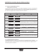
2.7.3.3 Remote Water Detector
Spot Type:
A remote spot type water detector requires three
conductors to be wired to the control terminal board
within the unit electrical box. The wire insulation must
be rated at 600V. The water detector provides pig-tail
leads for splice type wire connections with twist on
connectors (wire caps). Refer to the supplied electri-
cal diagram for proper wire terminations.
Strip/Cable Type:
A remote strip/cable type water detector is provided
with a two conductor cable harness with a quick
connect fi tting on the end. The harness mates to the
fi tting on the water detector and connects it to the
control board inside the electric box. Refer to the
supplied electrical diagram for proper wire termina-
tions.
2.7.4 Air-Cooled Split Systems
The following system interconnecting fi eld wiring
sections detail the number of conductors required for
a typical system. Additional control conductors may
be required depending on the options purchased with
the equipment. Refer to the supplied electrical dia-
gram to determine the total number of interconnect-
ing conductors required for your system. It is impor-
tant to note that the control transformer(s) supplied
with the equipment have been sized and selected
based upon the expected loads for each system.
CAUTION
Do not connect any additional loads to the
system control transformers. Connecting ad-
ditional loads to the factory supplied control
transformer(s) may result in overloading of the
transformer.
NOTE
All wiring must be provided in accordance with
local and national electrical code requirements
for Class 2 circuits.
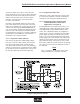
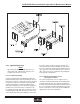
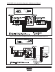
2.7.4.1 Remote Condenser (See Figure 9)
Systems equipped with a remote condenser require
fi eld wiring between the evaporator system and the
remote condenser. Refer to the supplied electrical
schematic and the wiring diagram supplied with the
condenser (typically located in the condenser electric
box). The installer must provide main power wiring to
the main power distribution block located within the
remote condenser control box. A separate equip-
ment ground lug is provided within the electrical box
for termination of the earth ground wire.
The installer must also wire two control conductors
from the terminal board within the evaporator unit to
the control terminal board within the remote con-
denser control box. Refer to the supplied electrical
diagram for proper wire terminations.
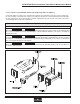
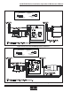
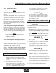
2.7.4.2 Remote Condensing Unit
(See Figure 10 and 11)
Systems equipped with a remote condensing unit re-
quire fi eld wiring between the evaporator system and
the remote condenser unit. The number of conduc-
tors required between the two systems varies based
upon the number of options provided. A single stage
cooling system typically requires three conductors.
Refer to the supplied electrical diagram(s) to deter-
mine the exact amount of fi eld wires and proper wire
terminations required for your specifi c unit.
2.7.5 Water/Glycol Systems (See Figure 12)
The following system interconnecting fi eld wiring
sections detail the number of conductors required for
a typical system. Additional control conductors may
be required depending on the options purchased with
the equipment. Refer to the supplied electrical dia-
gram to determine the total number of interconnect-
ing conductors required for your system. It is impor-
tant to note that the control transformer(s) supplied
with the equipment have been sized and selected
based upon the expected loads for each system.
CAUTION
Do not connect any additional loads to the
system control transformers. Connecting ad-
ditional loads to the factory supplied control
transformer(s) may result in overloading of the
transformer.
NOTE
All wiring must be provided in accordance with
local and national electrical code requirements
for Class 2 circuits.
Systems equipped with a glycol-cooled system/pump
package require fi eld wiring between the glycol unit and
pump package. The installer must wire two control con-
ductors from the terminal board within the glycol unit to
the pump package electrical box. Refer to the supplied
electrical schematic for proper wire terminations.