
Operator`s manual

(Mar, 2012)
CeilAiR OHS Series Installation, Operation & Maintenance Manual
A
ir Technology Systems, Inc.
3.0 Start-Up / Commissioning
3.1 Operation
For new installations, ensure the unit is ready to
operate by going through the completed installation
checklist provided with the unit, prior to start-up.
NOTE
Warranty Registration and Start-Up Checklist
should be completed during start-up and sent
to SATS. This checklist should be used as a
guideline for items that need to be checked
during start-up.
Start-up must be performed by a journeyman, refrig-
eration mechanic or an air conditioning technician.
3.2 Step by Step Start-Up Instructions
CAUTION
For air-cooled outdoor condensers, apply
power to condenser eight hours before operat-
ing system. This time is required to allow liquid
refrigerant to be driven out of the compressor.
The compressor crank case heater is energized
as long as power is applied to the unit.
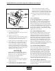
1. Replace all equipment, access panels and ceil-
ing panels removed prior to performing start-up
checks.
2. Apply power to start the CeilAiR OHS system at
the service disconnect switch, then turn the A/C
system on at the controller.
NOTE
The compressor may have a time delay on start-
up.
3. Ensure that all blowers and fans are rotating
freely and without any unusual noise.
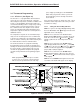
Water/Glycol-cooled units have a head pres-
sure water regulating valve that has been fac-
tory set. A valve adjustment may be required
based on water temperatures or water/glycol
fl ow conditions at your site. (Refer to System
Settings and Adjustments.)
If you have selected a dual circuit unit, both
refrigeration circuits must be tested at start-up.
There are several ways to force the second cir-
cuit into operation. If a microprocessor controller
was purchased it allows the unit to be placed in
a manual mode, refer to the separate Controller
Operations Manual sent with your unit.
4. Test cooling operation by setting the temperature
setpoint below the actual room temperature. The
compressor should come on and the discharge
air should feel cooler than the return air.
5. Test heating operation by setting the temperature
setpoint above the actual room temperature. The
source of heat should be energized to increase
discharge air temperature.
6. Test humidifi cation operation by creating a
demand for humidifi cation. Use an amp meter to
determine current draw of the humidifi er. Visually
check for vapor leaving the steam head or feel if
the cylinder is warm to verify if the humidifi er is
operational. In all cases, 1 to 6 hours might be
required to see a desired level or rise in humidity
in the conditioned space. Once room conditions
have been programmed or set, a repeat visit to
the conditioned space may be required to ensure
the humidifi er is meeting the room’s require-
ments.
7. Test dehumidifi cation operation by creating a
demand for dehumidifi cation. If necessary, set
the dehumidifi cation setpoint 10% below actual
room conditions, (the set point may already be
below actual room conditions, especially at start-
up). The chilled water valve should open to begin
the dehumidifi cation process. While in this mode,
room temperature may decrease and the reheat
function may activate. As conditions in the room
change, you may have to readjust the setpoint
as you check operation. An adequate heat load
within the space is required.
8. For Electric Reheat, use an amp meter on the
heater circuit to determine if the heater is op-
erational. For Hot Water Reheat, ensure the
control signal has energized the control valve
and the temperature of the water has decreased
as it passes through the unit. In all cases, 1 to 6
hours might be required to see a desired level or
decrease in humidity in the conditioned space.
Once room conditions have been programmed or
set, a repeat visit to the conditioned space may
be required to ensure the dehumidifi cation mode
is meeting the room’s requirements
.
3-1