CEL-FI QUATRA 4000 Installation and User Guide Revision: 3 draft Nextivity, Inc. 16550 West Bernardo Drive Building 5, Suite 550 San Diego, CA 92127 858-485-9442 www.cel-fi.
Table of Contents CONTENTS Table of Contents...........................................................................................................................................................2 Table of Figures ............................................................................................................................................................. 4 About This Guide .....................................................................................................................
Connecting Donor Source.................................................................................................................................... 21 Power ................................................................................................................................................................... 22 CU ...........................................................................................................................................................................
Table of Figures Figure 1. Architecture Overview ...................................................................................................................................8 Figure 3. NU Image ..................................................................................................................................................... 10 Figure 4. SMA Connectors on the NU ........................................................................................................................
About This Guide There are a variety of Cel-Fi QUATRA product variants available, supporting a variety of band configurations, for multiple regions. This manual is applicable to the Cel-Fi QUATRA 4000 ONLY, and does not apply to any other QUATRA variants. Safety Precautions Use Cel-Fi QUATRA 4000 indoors. It should not be used outdoors. These products are designed to be used with the power supply unit that shipped with the Network Unit.
Integrators and Carriers have partnered with Cel-Fi to deliver a smart solution designed for middleprise buildings – Cel-Fi QUATRA solutions. Cel-Fi provides the QUATRA BOM Estimator to help installers select the appropriate equipment in the right quantity, to eliminate the heavy cost / time of the (pre) planning effort. Cel-Fi’s all-digital, scalable, PoE Category cable-based solution makes it ideal for Single or Multi-Carrier environments.
Bands Supported Under This FCC Certification Verizon Band 4, 13 and 25 Sprint Support Band 2, 25 AT&T Support Band 4, 5, 12, 25 T-Mobile Support Band 4, 12, 25 7 12/6/2019
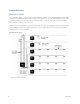
System Overview How Does It Work? Cel-Fi QUATRA 4000 is a powerful cellular signal distribution solution. Cel-Fi QUATRA 4000 is fundamentally comprised of a Network Unit (NU) and up to six (6) Coverage Units (per NU). The Network Unit takes the donor input from up to four (4) carrier signal sources. The signal source can be off-air (over-the-air (OTA)) from the macro network, or delivered via a small cell.
Cel-Fi QUATRA 4000 Key Features Carrier Grade, FCC-certified Smart Signal Booster Support for AT&T, Verizon, T-Mobile and Sprint Relays two (2) bands per operator, simultaneously Independent donor ports for each operator allows for independent antenna optimization Single combined (CU) server port enables driving either a serving antenna or passive DAS field 95-100 dB max system gain 140MHz total relay bandwidth o 6 channels x 20MHz o 2 channels x 10MHz Support for up to six (
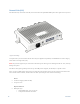
Network Unit (NU) The Network Unit, referred to as the NU, is the head end for the QUATRA 4000 system. The signal sources (one for Figure 2. NU Image each port/carrier) are connected to the NU. Then they are digitized and purified, and distributed over dual Category cables to the Coverage Units (CU). Note: Only cellular signals may be connected to the donor ports. Other types of radio signals will not work, and may damage the system. The NU has four (4) N-type RF ports on the top.
SFP+ module dock (future use) N-type Female RF Ports (4) for Donor Antenna o One for each carrier SMA port (2) o Provides an external antenna connection for the internal cellular modem (when used) Figure 3. SMA Connectors on the NU 11 User Interface LED interface (front) to indicate system status. (For detail on the LED go to LEDs.
Power Supply Cable Coverage Unit (CU) The Coverage Unit (CU) receives the digitized cellular signal from the NU, converts back to RF, amplifies, and distributes the service from its RF port. Service can be deployed through a single connected antenna, or through a DAS field. Figure 4. QUATRA 4000 CU The Coverage Unit includes a multiband blade-style antenna that can be connected directly to the CU. See Figure 8. CU Antenna Figure 5.
Figure 6. CU Server Antenna Accessories QUATRA 4000 Range Extender (QRE4K) Model Number: Q40-OE Figure 7.
The QRE-4K unit is a device that extends the standard 100 meter cable length from NU to CU by an additional 100 meters. It is inserted in-line between the NU and CU, and requires no external power. The RJ45 connectors are on each side (two per side). Figure 8. Using QRE-4K Donor Antennas The donor antennas are used to provide off-air signals to individual carrier donor input ports. The objective is to provide the best quality carrier signals to the NU.
Nextivity recommends its LPDA-R antenna for use as a great donor antenna for most situations. Figure 10. Cel-Fi LPDA-R antenna Check www.cel-fi.com/antennas for details and updates. Server Antenna The server antenna connects to the RF port on the CU. Figure 11. Server Antenna Connects A variety of Server antennas are available from Nextivity. Check www.cel-fi.com/antennas for updates.
The WAVE Portal Introduction Cel-Fi WAVE is Nextivity’s SOC2 Type 1 compliant cloud-based software platform from which Cel-Fi apps and connected capabilities are hosted and driven. Current-generation Cel-Fi products feature embedded connectivity that allows them to connect to the WAVE cloud. The WAVE portal and apps are used to facilitate software updates, registration, commissioning, installation, optimization, and troubleshooting. The Cel-Fi WAVE platform continues to expand in features and function.
The Main Alarms Error Indication Name Meaning ES1 NU HW Network Unit hardware error ES2 Not Receiving Signal Insufficient donor Signal ES3 CU HW Coverage Unit hardware error ES4 Input too strong Donor signal (RSRP) too strong ES5 NU Overheating Network Unit is overheating ES6 CU Overheating Coverage Unit is overheating ES7 Too Close Not applicable for QUATRA ES8 Too Far Not applicable for QUATRA ES9 Disabled by operator Not applicable for QUATRA ES10 Location Lock Not applica
Installation Important: Before any permanent installation, make sure all the components are planned and accounted for, as well as any wiring, cabling, power, mounting, antenna placements, and system access. Overview Several things need to be determined as part of installation planning and preparation. There isn’t a specific order these items need to be resolved. Depending on the specific needs at the site, varying orders of activity may be employed.
Caution: Make sure the area behind any surface is free of electrical wires or other dangerous elements prior to drilling. Figure 12. NU Mounting Illustration The QUATRA 4000 NU has four (4) secure mounting tabs, two on each side. The two topmost tabs have been keyholed. Note: The Mounting Instructions below use the standard drywall mounting anchors and screws included with the unit. If the NU is to be mounted onto other surfaces, make sure the appropriate anchors and screws are used (not included).
Figure 13, NU Mounting Template 1. 2. 3. 4. 5. 6. 7. 8. 9. 20 Option 2. No Template To mount the NU, first determine the approximate location on the wall for the unit. Hold the unit up on the wall and, using a pencil or similar marker, mark one of the top (right or left) points. Using a drill, drill the location for the wall anchor. Hammer in the wall anchor. Place the NU in the right location and screw on the mount.
Note: The keyhole style allows for fine-tuning of the horizontal level. Figure 14. Leveling the NU 10. 11. 12. 13. 14. With the NU attached to wall, drill holes for each remaining anchor. Unscrew the top two screws slightly, so the unit can be removed, but leave the screws in the wall. Remove the NU from the wall and hammer the bottom two drywall anchors into place. Hang the NU back on the top two screws and re-tighten those screws. Screw the bottom two screws into place, through each bottom tab hole.
Each donor antenna should be mounted safely and securely where it can access the desired cellular network. A coaxial cable connects the donor antenna to the NU’s RF port for each given carrier. Small Cell Donor If a small cell is used as the donor source then it should be connected at this time. The input signal level for the donor port should be between -60 and -50 dBm. Note: the small cell should be fully-operational in standalone mode prior to being connected to the QUATRA 4000.
4. 5. 6. Hammer in the anchors. Attach the bracket to the wall with the included screws. Once the bracket is firmly attached to the wall, the CU can be attached to the bracket. Figure 16. Attach CU to bracket 23 7. With the bracket in place, attach the CU. 8. Tighten (finger) each Locking Screw into place to ensure the CU is securely attached.
Connecting Server Antenna(s) Figure 17. Attaching antenna to CU The CU has an N-type connector on the top of the unit for attaching an antenna. An omni-directional antenna is included with each CU, or a coax cable can be connected with a series of passive antennas attached.
Connecting NU and CU Each CU connects to the NU using two Ethernet cables (Cat5e or better). Figure 18. CU port assignment on the NU Using a QRE If distances greater than 100 meters from NU to CU are required, an extra 100 meters can be achieved by inserting the QUATRA RANGE EXTENDER (QRE) between the NU and the CU. Note: Only the QUATRA 4000 RANGE EXTENDER may be used. The QUATRA 1000 and QUATRA 2000 QRE is not compatible with the QUATRA 4000.
NU LED Table LED Label LED State Meaning POWER NO LIGHT No power SOLID GREEN Powered and operating normally FLASHING GREEN Scanning to acquire network signals SOLID RED Hardware error FLASHING RED Error NO LIGHT Not connected properly, no power SOLID GREEN Connected, powered and operating normally SOLID GREEN SFP+ module installed, and communicating properly FLASHING GREEN SFP+ module installed, not communicating SOLID GREEN Link is up FLASHING GREEN Link is up and active SOLID GRE
The meaning for each LED on the CU is shown in the table below.
Diagnostics and Testing WAVE PRO and COMPASS Introduction COMPASS is a hand-held battery operated device specifically designed to simplify the installation of all QAUTRA variants, without the need for an Internet connection to the WAVE Portal in the cloud. NOTE: The WAVE Portal is a very powerful and time saving system. Nextivity highly recommends that you still connect your QUATRA systems to the Internet for WAVE Portal remote management, alarms, and diagnostics.Note: COMPASS has its own User Manual.
Figure XX Cel-Fi QUATRA 4000 connected to COMPASS Band Settings 1. All Cel-Fi QUATRA variants will select bands and channels to relay automatically. 2. Optionally, bands may be enabled/disabled using the Bands Settings feature using COMPASS and the WAVE Pro app. a. Click on “Bands Settings” b.
CEL-FI QUATRA OPTIMIZATION FEATURES Antenna Positioning The QUATRA 4000 system can accept up to four individual donor signals. One per carrier. Each donor can be established to the system either via small cell or off-air. When using an off-air signal, a directional antenna is recommended to provide the best signal quality. (Nextivity offers a number of directional antennas that can be used. See www.cel-fi.com/products for details.
Speed Test This feature tests the speed of the current Network Carrier of the SIM card inserted into the COMPASS. 1. 2. In the WAVE PRO app, go to the “Optimization” section and press the "Speed Test" button. Click on “Start,” and The Cel-Fi COMPASS will gather data for several minutes and display the results below. Step 1 Step 2 Serving Cell Report The Serving Cell Report is a live reading of the current Network Carrier of the SIM card inserted into the Cel-Fi COMPASS.
Advanced Information. Antennas and QUATRA 4000 Donor Antennas Donor Signals A good donor signal, arriving as cleanly as possible, to the NU, is perhaps the most important consideration in driving the best experiences and outcomes with QUATRA 4000. With regard to 4G LTE, there are two metrics of particular importance to monitor and optimize: 1. RSRP. Reference Signal Receive Power. It is the power of the LTE Reference Signals spread over the full bandwidth and narrowband.
3. How strong is the serving signal? Although Cel-Fi QUATRA 4000 has the highest gain of any antenna in its class, if the serving signal is extremely weak, then a high-gain antenna may be required to connect the uplink calls and to get the optimal DL power on the serving side. Grounding and Lightning Protection Installers of Cel-Fi QUATRA 4000 are encouraged to follow the lightning protection guidelines documented in the National Electrical Code (NEC) and NFPA 780, and/or local codes.
Note: The Cel-Fi QUATRA 4000 Coverage Unit is plenum rated.
Specifications QUATRA 4000 OPERATOR’S CONFIGURATIONS OPERATORS AT&T, Sprint, Verizon, TMobile Bands: QUATRA 4000i (Part 20) 4,5,12,13,25 OPERATOR 1 Verizon OPERATOR 2 Sprint RELAY CONFIGURATIONS (one configuration per operator) OPERATOR 3 T-Mobile OPERATOR 4 AT&T TRANSMIT EVM UL HARDWARE – READY REGULATORY CERTIFICATIONS FCC VERIZON RADIO SPECS 35 Operators Supported 8.5% 8.
BAND 25 SPRINT BAND 5 BAND 4 T-MOBILE BAND 12 BAND 25 AT&T 36 BAND 4 Downlink (DL) Frequency (MHz) Uplink (UL) Frequency (MHz) Relay Bandwidth (Max)(MHz) UL Output Power (at port)(dBm) DL Min Input Level (dBm RSRP) DL Max Input Level (dBm RSSI) System Gain (Max)(dB) Downlink (DL) Frequency (MHz) Uplink (UL) Frequency (MHz) Relay Bandwidth (Max)(MHz) UL Output Power (at port)(dBm) DL Min Input Level (dBm RSRP) DL Max Input Level (dBm RSSI) System Gain (Max)(dB) Downlink (DL) Frequency (MHz) Uplink
BAND 12 BAND 25 BAND 5 RETURN LOSS (DB) At all ports DONOR ANTENNAS COVERAGE UNIT CONFIGURATION TO NETWORK UNIT USER INTERFACE Coverage Unit Support POE - PSE Power / Status CU Link Donor Antenna Cellular Modem Ethernet USB Dimensions MECHANICAL 37 DL Max Input Level (dBm RSSI) System Gain (Max)(dB) Downlink (DL) Frequency (MHz) Uplink (UL) Frequency (MHz) Relay Bandwidth (Max)(MHz) UL Output Power (at port)(dBm) DL Min Input Level (dBm RSRP) DL Max Input Level (dBm RSSI) System Gain (Max)(dB) D
ENVIRONMENTAL Maximum Surface Temperature (°C) Measured at 30°C Ambient 44 STANDARDS FCC ENVIRONMENTAL RADIO SPECS ISED UL 3GPP Repeater Specs Operating Temperature Ambient Relative Humidity Non-Condensing Ingress Protection (IP) COVERAGE UNIT Downlink (DL) Frequency (MHz) Frequency Uplink (UL) Frequency (MHz) DL Power (dBm) Per Band NETWORK UNIT INTERFACE USER INTERFACE MECHANICAL Power / Status NU Link Dimensions Mounting 38 Part 15, 22, 24,27,20 Yes Yes Yes Yes 0–40°C 0–95% 40 617–2690 663–2
Trademarks Cel-Fi, IntelliBoost, and Nextivity logo are trademarks of Nextivity, Inc. Warranty & Limitation of Liability Nextivity Inc., provides a limited warranty for its products. For details, please refer to http://cel-fi. com/warranty.
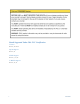
Troubleshooting Alarm Table 40 Network Unit Hardware Error Network Unit Hardware Error - Power cycle the Network Unit (NU) and check for software updates. If problem persists, return NU for service. Insufficient Donor Signal Insufficient Donor Signal - Relocate Network Unit (NU) where a stronger signal exists, or use an external antenna for the NU. If using a small cell, verify the small cell can process calls and check the connections to the NU. Power cycle the NU.
Small Cell Detected Small Cell Detected - Small Cell Detected but Network Unit (NU) is not set to Small Cell. Use the WAVE Portal to set NU Mode to Small Cell. Antenna Configuration Error Antenna Configuration Error - Too Many Coverage Units (CU) connected. More than one CU in use for Off-Air configuration. Use the WAVE Portal to set Mode to External Antenna, and NU should be connected to an external antenna. Antenna Positioning Required Antenna Positioning Required - Antenna positioning incomplete.