User Guide including AutoMaker ™ Version 1.4 www.cel-robox.
Contents 1.0 Introduction ��������������������������������������������������������������������������6 1.1 Welcome ������������������������������������������������������������������������������������������������ 7 1.2 Learn More ��������������������������������������������������������������������������������������������� 7 1.3 Using This Guide ����������������������������������������������������������������������������������� 8 1.
Contents 3.6 Attaching the Power Cable and Powering On ���������������������������������� 33 4.0 Using Robox® ����������������������������������������������������������������������34 4.1 Loading Filament ������������������������������������������������������������������������������� 35 4.1.1 Preparing the Filament ��������������������������������������������������������������������������� 35 4.1.2 Feeding to the Head �������������������������������������������������������������������������������� 35 4.1.
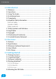
Contents 5.4.1 Arranging Items on the Bed ������������������������������������������������������������������� 54 5.5 Settings Screen ������������������������������������������������������������������������������������ 56 5.5.1 Starting Production ���������������������������������������������������������������������������������� 56 5.5.2 Filament Settings �������������������������������������������������������������������������������������� 57 5.5.
Contents 7.2.6 Build Chamber ������������������������������������������������������������������������������������������ 93 7.2.7 Extruder ������������������������������������������������������������������������������������������������������� 93 7.2.8 Lubrication ������������������������������������������������������������������������������������������������� 94 7.3 Troubleshooting ���������������������������������������������������������������������������������� 95 8.
1.0 1.
1.0 Introduction 1.1 Welcome Thank you for purchasing the Robox® micro-manufacturing platform and welcome to the future of custom manufacturing! Robox® provides you with the capability to produce three-dimensional models in a variety of thermoplastic materials and with our HeadLock™ easy replacement system, you can begin to explore a whole range of personal manufacturing possibilities. 1.2 Learn More Refer to the following sources for additional information and for product and software updates.
1.0 Introduction 1.3 Using This Guide This user guide contains the information you need to setup and use your Robox® micro-manufacturing platform. 1.3.1 How This Guide Is Organised This guide contains the following parts: • Section 1 - Welcome This section outlines all the important safety considerations, international certifications and information on this user guide and accompanying documentation.
1.0 Introduction • Section 8 - Supplementary Information This final section contains a variety of extra information for your reference. It includes a GCode reference, glossary of terms, FAQs and contact details. 1.4 Instructional Icons The following classifications are used throughout this guide: • DANGER/WARNING: Important information to prevent injury or damage to yourself, people or property when trying to complete a task.
1.0 Introduction 1.5 Typography Bold text Indicates a menu or item to select. Italics Used to emphasise a word or phrase. Keys enclosed in the less-than and greater-than sign means that you must press the enclosed key. Example: means that you must press the Enter or Return key. + If you must press two or more keys simultaneously, the key names are linked with a plus sign (+).
1.0 Introduction Operation Safety • Before using the product, ensure all cables are correctly connected to a power • • • • • • • • • • • supply that matches the rating label and the power cables are not damaged. If you detect any damage, contact your retailer immediately. Do not place the product in any area where it may become wet or damp and avoid dusty, humid and high temperature environments which could negatively affect product performance.
1.0 Introduction 2 12 Safety Guidelines • Follow all safety rules in this section and observe all cautions and warnings in • • • • • • • • this guide (and those from any additions and materials used in conjunction with the product). Before using the product, carefully read and understand all the manuals that were included with the package. Check for updated versions on our website. Do not modify any safety features or make modifications to Robox®.
1.0 Introduction 1.7 Safety Symbols and Definitions The safety symbols are used throughout this guide and on product warning labels: • Hot Surface Hazard: Information to prevent injury to yourself when trying to complete a task. • Caution: Indicates a pinch point hazard that could cause person injury. • Caution: Indicates an area which carries risk of electric shock disconnect from the power outlet before accessing. • Corrosive: Used on materials which may be corrosive and cause harm to skin and/or eyes.
1.0 Introduction 1.8 Legal Notice The only warranties for CEL Technology products and services are set forth in the express warranty statement accompanying such products and services. Nothing herein should be construed as constituting an additional warranty. CEL Technology shall not be liable for technical or editorial errors or omissions contained herein. 1.9 Copyright 4 14 © 2017 CEL Technology Ltd. All rights reserved. Robox is a registered trademark of CEL Technology Ltd.
1.0 Introduction 1.10 Declaration of Conformity Manufacturer: CEL Technology Ltd. Unit 1604, 16/F Nan Fung Commercial Centre, 19 Lam Lok Street, Kowloon Bay, Hong Kong UK Representative: C Enterprise (UK) Ltd.
1.0 Introduction 1.11 Limited Warranty Statement CEL Technology Ltd. (“CEL”) warrants its systems and associated peripheral devices and replacement parts (collectively, the “Product”) purchased from CEL or an Affiliated/Authorised CEL Reseller to be free from defects in material and workmanship according to the terms and conditions stated below: Warranties extend only to the original purchaser of the Product.
1.0 Introduction designated by CEL. No coverage or benefits under this Limited Warranty will exist if any of the following conditions apply: a. The Product has been subjected to abnormal use, improper or inadequate maintenance, unauthorised modifications, unauthorised repair, exposure to moisture, electrical problems associated with incoming power, or other acts which are not the fault of CEL Technology Ltd. b.
1.0 Introduction 1.12 Regulatory and Environmental Information 8 18 1.12.1 FCC Statements (U.S.A.) The U.S. Federal Communications Commission (in Title 47 CFR Part 15 Subpart B - Unintentional Radiators) has specified that the following notices be brought to the attention of users of this product. This device complies with part 15 of the FCC rules.
1.0 Introduction 1.12.4 Disposal of waste equipment by users in private households in the European Union (WEEE) This symbol on the product or on its packaging indicates that this product must not be disposed of with your other household waste. Instead, it is your responsibility to dispose of your waste equipment by handing it over to a designated collection point for the recycling of waste electrical and electronic equipment.
2.
2.0 Overview 2.1 Features • • • • • • • • • • QuickFill™ Dual Nozzle Technology Auto Z Height Calibration ‘TapeLess’ High Performance PEI Bed Material HeadLock™ quick change head system Single or Dual Extruders Automatic Material Recognition (SmartReel™) and Instant Loading Automatic Head Recognition Draft Blocking Build Chamber 2 minute Fast Heat-up Time Plug and Play - no set up or assembly required 2.2 Specifications 2.2.
2.0 Overview 2.2.5 3D Printing Head • Print Technology: • Build Size (LxWxH): • Layer Resolutions: • Positioning Precision: • Filament Diameter: • Nozzle Diameters: • Model Materials: • Support Materials: Fused Filament Fabrication (FFF) 210 x 150 x 100mm (8.3 x 5.9 x 3.9 in) Super (20 microns / 0.0008 in) High (100 microns / 0.0039 in) Standard (200 microns / 0.0078 in) Low (300 microns / 0.0118 in) XY: 7.5 microns (0.0003 in) Z: 0.15625 microns (0.000006 in) 1.
2.0 Overview 2.4 How It Works 2.4.1 3D Printing When Robox® is using the 3D printer head, it uses a technology known as Fused Filament Fabrication (FFF). This works in a similar way to a hot-melt glue gun using plastic filament instead of glue sticks. The feedstock for the print head is 1.75mm thermoplastic filament which is supplied on a reel for installing into the printer.
2.0 Overview 2.5 At A Glance 4 24 This section highlights all the major features of Robox®. 12 13 6 3 1 10 8 7 2 9 11 4 5 14 1 2 3 4 5 6 7 Print Head X Carriage X Axis Rails Print Bed Y Axis Rail Z Axis Rail and Drive Screw Z Carriage (Right) 8 9 10 11 12 13 14 X Axis Belt Tip Wipe Blade Reel Hub Cover Door Interlock Latch Enclosure Door Internal Ambient Lighting Front Tray Cover www.cel-robox.
2.0 Overview This view shows the rear connections of Robox® and the SmartReel™ location. 8 7 5 1 2 9 6 3 4 1 2 3 4 5 microSD Card Flash Storage USB Type B Socket Power Switch C5 ‘Cloverleaf’ Power Inlet Robox® SmartReel™ 6 7 8 9 Pause/Resume/Eject Button Outlet Vents Door Side Cover • Although there is a microSD card accessible from the back of Robox®, this cannot be read by any other machine and is only for use as internal flash storage - access is provided only for diagnostic/repair purposes.
3.
3.0 Getting Started 3.1 Package Contents Check your product package for the following items. 2m USB A-B Cable IEC C5 Power Cable Robox® PE NING WI E hol D CLEArop BECLEANING yl Alco BED ANING WIP Isop hol 70%BE D CLEWIPE l Alco 70% Isopropyl Alcohol USE IsopALropy 70%MEDIC NOT FOR NOT FOR MEDICAL USE FOR MEDICAL NOT 0197 USB Flash Drive Tweezers 0197 USE 0197 10x Bed Wipes Set of 4 Cleanup Tools Safety Information Version 1.0 www.cel-robox.
3.0 Getting Started 3.2 Unpacking Robox® 8 28 This section explains how to safely unpack your new Robox® and get it ready for production! Your new micro manufacturing platform has been carefully assembled and packaged at our factory to arrive with you in perfect condition. Please follow the instructions below carefully to avoid causing any damage. 9. Carefully cut the tape along the top of the box, being careful not to cut too deep, and open the box. 10.
3.0 Getting Started 12. Remove the packing tape which is used to secure the door. 13. Next, remove the 3D printed packing clip which is used to secure the printhead, Z-carriage and bed during shipping. 14. Ensure that the head and bed are free to move before proceeding. You can move them both by hand to check. • We recommend that you keep hold of all of your packaging materials should you need to return any parts to us. www.cel-robox.
3.0 Getting Started 3.3 Software Installation 0 30 This section explains in detail how to install the AutoMaker™ software package for controlling your Robox®. The included USB card drive contains this software and an electronic version of this document, as well as some sample .stl files for you to print. These steps may vary slightly depending on your operating system, all provided screenshots and instructions are from Windows 8.1 for reference. 1.
3.0 Getting Started 5. The installer will start, click Next > to continue. 6. Please carefully read the Licence Agreement and select ‘I accept the agreement’, then select Next > to continue. 7. Please choose where you would like to install AutoMaker™ either by typing the path directly, or by clicking the button. Click Next > to continue and accept the path and begin the installation. N.B. To facilitate future support we recommend using the default install location. 8.
3.0 Getting Started 3.4 Starting AutoMaker™ 2 32 This section explains how to start AutoMaker™ on all supported operating systems. 3.4.1 On Windows To start AutoMaker™, double click on the icon shown below on your desktop: It can also be launched using the Start Menu in the normal way - it can be found under ‘CEL’. 3.4.2 On MacOS To start AutoMaker™, click the icon which has been added to your dock. It can also be found under Applications in Finder. 3.4.
3.0 Getting Started 3.5 Attaching the USB Cable Robox® comes supplied with a 2 metre USB Type A-Type B cable for connecting to your PC. Please connect as shown. • DO NOT connect your Robox® until you have been through the software installation steps on the previous page and started AutoMaker™. 3.6 Attaching the Power Cable and Powering On Connect the supplied AC power lead to Robox® and switch on using the rear power switch.
4.
4.0 Using Robox 4.1 Loading Filament This section explains how to load your chosen 3D printing plastic filament into Robox® ready to produce your first print! It is designed to be a very simple process with most functions taking place automatically. 4.1.1 Preparing the Filament Before attempting to load filament, it is advisable to cut the end cleanly at a rightangle. This will allow the filament to enter the extruder and melt chamber more easily. 4.1.
4.0 Using Robox 6 36 4.1.3 Installing the Reel Finally, install the SmartReel™ into the dock, you should hear a click when it is correctly located, and it should appear as a recognised reel in AutoMaker™. Congratulations! - you’re now ready to print. www.cel-robox.
4.0 Using Robox 4.2 Unloading Filament This section explains how to remove a reel of filament for storage or to change to a different colour/material. This process has also been designed to be as simple as possible, and can even be undertaken mid-print! 4.2.1 Pause / Resume / Eject Button There is a button in the centre of the reel when installed which has three functions - Pause, Resume and Eject. To pause the print, simply press this button once, and to resume press the button again.
4.0 Using Robox 4.2.2 Removing The Reel Once the extruder motor has stopped, your filament has been fully ejected. Press the two metal buttons on the top and bottom of the reel hub and pull the reel away from the machine. Coil any extra material onto the reel - the loose end can easily be held by weaving in and out of the holes in the rim. 11 2 4.3 Filament Storage 8 38 Most plastics, including ABS and PLA are ‘hygroscopic’ in nature i.e. they absorb water from the surrounding environment.
4.0 Using Robox 4.4 The HeadLock™ System This section explains how to change the head on Robox® allowing you to change its functionality. The base model comes supplied with the Dual Nozzle, Single Material head for FFF 3D printing. All future head designs will make use of the same interface, and the HeadLock™ system has been designed to make head replacement quick and easy. A microchip in each head also allows AutoMaker™ to automatically identify what head is installed, and set itself up appropriately. 4.
4.0 Using Robox 0 40 Once unscrewed, pull down the head as shown in the diagram below - you will hear a ‘snap’ as the head disconnects. 1 2 4.4.2 Installing a Head To install a new head into Robox®, the process is essentially the same in reverse. First, push the bottom of the head into the carriage until you hear/feel a ‘snap’ - this signifies the head is correctly aligned and located, then simply tighten the locking wheel until fully tight.
4.0 Using Robox 4.5 Removing the Bed To remove the PEI bed from your Robox®, simply slide the handle on the front of the bed (highlighted in blue) to the left to release. Then lift up the front edge of the board using the finger recess (shown by the hand) and slide the bed towards you. 4.
5.
5.0 AutoMaker Software 5.1 User Interface This section outlines the major elements which make up the AutoMaker™ user interface. There are basically 3 separate screens - Status, Layout and Settings. • Status Screen - This page displays the current status of the selected printer. It shows what it’s doing, what filament and head are installed, as well as extra information on temperatures etc. • Layout Screen - This page is used for laying out the 3D models of objects you’d like to print.
5.0 AutoMaker Software 5.2 Print Workflow 4 44 • AutoMaker™ is continually being improved - please check our website for an updated version of the user manual if you require further information. www.cel-robox.
5.0 AutoMaker Software 5.3 Status Screen This section explains the status screen in more detail. 4 5 1 6 2 9 3 7 1 2 3 4 5 Connected Printers Installed Filament Temperature Display Projects Tabs Preferences 6 7 8 9 10 8 10 Current Printer Status Unlock Door Eject Filament Display Advanced Settings Go To Settings Screen 5.3.1 Connected Printers This area of the screen displays the status of all printers which are currently attached to your PC. Ready Printing Paused Notification Error www.
5.0 AutoMaker Software 6 46 Each Robox® connected to AutoMaker™ has its own icon which displays the name and current status of the printer, as well as an indicator which shows the progress of the current print (if available). The status icons can be summarised as follows: • • • • • Ready - When Robox® is available and ready to print. Printing - When Robox® is currently printing an object. Paused - When Robox® has been paused during a print.
5.0 AutoMaker Software 5.3.4 Projects Tabs This part of the screen shows the currently available print jobs. On starting, AutoMaker™ will create an empty project and load any projects which weren’t closed on the previous run. Other functions are summarised below: - Creates a new project file - Displays the context menu explained below Rename Export Email Upload - Change the name of the project - Export the selected project as a .
5.0 AutoMaker Software 8 48 5.3.6 Advanced Settings This part of the screen allows you to perform more advanced functions relating to the overall printer - print job settings are accessed from the Settings Screen see section 5.5.
5.0 AutoMaker Software 5.3.7 Advanced Settings - SmartReel™ Programming This page is for writing custom material parameters to a Robox® SmartReel™. Simply choose which reel to apply the settings to, choose a material from the list - custom or official, then click the Program Reel button. 1 2 3 4 1 Apply to Reel Hub 1 2 Apply to Reel Hub 2 3 Material Selection 4 Program Reel 5.3.
5.0 AutoMaker Software 0 50 5.3.9 Advanced Settings - Calibration and Maintenance This page is for executing a wide range of ‘macros’ (small GCode programs that execute sequentially) and for access to machine calibration - see section 7.1.
5.0 AutoMaker Software cable as they are executed. • Clean Nozzles This executes a short GCode ‘macro’ that makes use of the Tip Wipe blade at the front of the bed, and as such should only be executed when the bed is clear of objects. You can choose to clean either the fill or the fine nozzle. • Purge Material This executes the purge routine, which is used when changing between two dissimilar materials - see section 7.2.1.
5.0 AutoMaker Software 2 52 5.3.10 Advanced Settings - Diagnostics This page is really only intended for diagnosing possible faults with your Robox®. It displays the serial numbers of the printer and the head which will be required when contacting CEL support. It also displays the state of all of the microswitches in the printer so that you can verify they are functioning correctly.
5.0 AutoMaker Software 5.4 Layout Screen This section explains how to lay out objects on the bed and prepare for printing.
5.0 AutoMaker Software 4 54 Rotate View (click and drag) + Pan View (click and drag) Zoom (scroll wheel) Select and manipulate models + Select multiple models 5.4.1 Arranging Items on the Bed This section explains the layout function of the software which allows you to arrange your 3D models on the bed ready for printing. It is designed to be very simple, requiring only the following buttons: Undo Step back through the history of layout operations you have completed i.e.
5.0 AutoMaker Software Lay Flat Auto Layout Group • This is for reorienting your model to the build plate. Click the button, and then select a surface on the model that you would like to lay flat to the bed. This automatically arranges all models on the bed with sufficient clearance between them and no interference. This used to collect multiple objects together into one selection. When a group is selected, this button will toggle to ‘Ungroup’.
5.0 AutoMaker Software 5.5 Settings Screen 6 56 This section explains the basic settings page of the software which allows you to choose quality options and materials for your print. 6 7 1 3 2 4 1 2 3 4 5 Filament Settings Print Settings Advanced Settings Return to Layout Screen 5 Start the production (Make!) 6 Return to Status Screen 7 Model Display 5.5.
5.0 AutoMaker Software 5.5.2 Filament Settings This part of the screen displays what colour and type of filament is currently installed in the machine and allows you to choose and create custom material profiles. It will also show you how much material is remaining on each reel.
5.0 AutoMaker Software 8 58 5.5.3 Print Settings This allows you to adjust the quality and print profile for production. 1 2 3 4 5 6 1 Quality Setting 2 Custom Print Profile 3 Profile Summary 4 Fill Density 5 Support Material Setting 6 Brim Width • Quality Setting This allows you to select a basic quality setting from the list of options - Draft, Normal or Fine. The final option - Custom allows you to create a new profile or to select from a previously created one.
5.0 AutoMaker Software • Fill Density This setting allows you to choose how ‘solid’ you would like the finished object to be. The fill pattern can also be changed using a custom profile - see section 5.5.6. 90% Fill 80% Fill 70% Fill 60% Fill 50% Fill 40% Fill 30% Fill • Support Material This switch toggles the printing of support material. If you are printing a part with large overhangs, you may wish to print structures at the same time to support the object. Support settings (e.g.
5.0 AutoMaker Software 0 60 5.5.4 Advanced Settings - Material This section explains the advanced page, and it’s associated functions and options. 1 2 3 4 5 6 7 8 9 10 11 12 1 2 3 4 5 6 Material Name Material Type Material Colour Filament Diameter Filament Multiplier Feed Rate Multiplier 7 8 9 10 11 12 Bed Temperature Bed Temperature (1st Layer) Nozzle Temperature Nozzle Temperature (1st Layer) Ambient Temperature Help Text www.cel-robox.
5.0 AutoMaker Software • Material Name This field can be used to name the material profile - this will be displayed on the Status page when the reel is installed in the dock. • Material Type Pick the material type here from the list of available options, or type the name of the material yourself. • Material Colour Pick the material colour here, or choose custom to define your own colour.
5.0 AutoMaker Software 2 62 • Nozzle Temperature (°C) This value sets the temperature of the nozzle used for printing the material. Different thermoplastics require different nozzle temperatures due to their differing melting points (or more accurately, glass transition temperatures). For example, most ABS requires a nozzle temperature of 240°C, whereas PLA only requires 200°C to print successfully.
5.0 AutoMaker Software 5.5.5 Advanced Settings - Print Profile This section explains the advanced page, and it’s associated functions and options: 1 2 1 Advanced Extrusion Settings 2 Advanced Nozzle Settings 3 Advanced Support Settings 3 4 5 4 Advanced Speed Settings 5 Advanced Cooling Settings • Advanced Extrusion Settings This allows you to adjust advanced printing profile parameters relevant to extrusion e.g. layer height, fill density and fill pattern - see section 5.5.6.
5.0 AutoMaker Software 4 64 5.5.6 Advanced Settings - Extrusion These settings allow you to adjust all the parameters which affect the extrusion of plastic and generally relate to print quality and speed. By tuning these values, users can control the appearance, strength and surface finish of objects, as well as dramatically affecting print speed by varying layer height, fill pattern, density and perimeters. 1 2 3 4 5 6 7 8 1 2 3 4 Layer Height Fill Density Fill Pattern Infill Every ...
5.0 AutoMaker Software • Layer Height (mm) This setting defines the layer height (essentially the print resolution) of the printed object. Users can select from any value between 20-400µm, however this setting will dramatically affect print time as shown in the below illustration: Print Representation (1.
5.0 AutoMaker Software 6 66 • Number of Perimeters This setting specifies how many outside walls are produced to complete the exterior surface of the part. The more perimeters, the thicker the part walls. • Brim Width This is explained in ‘Print Settings’ - see section 5.5.3. • Help Text This box displays a brief explanation of the setting which is highlighted (changes on mouseover). www.cel-robox.
5.0 AutoMaker Software 5.5.7 Advanced Settings - Nozzles These settings allow you to adjust all the parameters which affect the operation of the nozzles and needle valves. By tuning these values, users can control the appearance of start/stop points and surface finish, as well as dramatically affecting print speed through the use of the larger fill nozzle.
5.0 AutoMaker Software 8 68 • Perimeter Nozzle Selection This setting allows you to choose which nozzle is used to print the exterior surfaces (perimeters) of the part - choose from 0.3mm (fine nozzle) or 0.8mm (fill nozzle). • Fill Nozzle Selection This setting allows you to choose which nozzle is used to print the internal filling of the part - choose from 0.3mm (fine nozzle) or 0.8mm (fill nozzle).
5.0 AutoMaker Software • Retract Length (mm) This value specifies the distance the filament is ‘pulled back’ (retracted) at the end of an extrusion path. This is used to release pressure before the needle valve begins to close. • Retract/Unretract Speed (mm/s) This value specifies the speed that the filament is ‘pulled back’ (retracted) at the end of an extrusion path and also pushed back in (unretracted) at the start of the next.
5.0 AutoMaker Software 0 70 5.5.8 Advanced Settings - Support This settings page allows you to adjust all the parameters which affect the automatic generation of support material. Support material is required where objects are being built in mid-air due to an overhang. 1 2 3 4 5 6 7 1 2 3 4 Generate Support Material Overhang Threshold Force Support for First ...
5.0 AutoMaker Software • Support Pattern This option allows you to set the pattern used to generate the support material - with some options requiring less material, giving faster print times. Rectilinear Grid Rectilinear Honeycomb Pillars • Pattern Spacing (mm) This specifies the spacing in millimetres between support extrusions i.e. the density of the support material. • Pattern Angle ( ° ) This option allows the direction of the support lines to be rotated in the XY plane.
5.0 AutoMaker Software 2 72 5.5.9 Advanced Settings - Speed This settings page allows you to adjust all the parameters which affect the speed of printing. There are individual settings for various parts of the print including perimeters, bridges, and infill. By tuning these values, users can control the appearance of printed objects and optimise speed vs. quality.
5.0 AutoMaker Software • Perimeter Print Speed (mm/s) This parameter sets the speed at which perimeters (the walls of the object) are printed in millimetres per second. • Small Perimeter Print Speed (mm/s) This parameter sets the speed at which small perimeters (meant for holes, islands and fine details) are printed in millimetres per second. A slower speed than ‘Perimeter Print Speed’ is recommended for improved quality of small details.
5.0 AutoMaker Software 4 74 • Bridges Print Speed (mm/s) This parameter sets the speed at which bridges (unsupported layers between two existing surfaces) are printed in millimetres per second. The ability to span unsupported areas depends on the material and cooling. Going too slow will result in sagging, too fast will result in broken strands. Generally bridging runs slower than perimeters.
5.0 AutoMaker Software 5.5.10 Advanced Settings - Cooling This settings page allows you to adjust all the parameters which affect automatic cooling of the part as it prints. Layers must be cooled sufficiently before another layer is applied to prevent dimensional inaccuracy and ‘squishy’ small layers. 1 2 3 4 5 6 7 8 9 1 2 3 4 5 Enable Automatic Cooling Minimum Fan Speed (%) Maximum Fan Speed (%) Bridges Fan Speed (%) Disable Fan for First ...
5.0 AutoMaker Software 6 76 • Enable Automatic Cooling This setting is used to enable or disable automatic cooling for 3D prints. AutoMaker™ uses one of two methods to control cooling - it can either increase the fan speed or slow down the time to print a layer. The choice of which method is used is controlled by ‘Enable Fan if Layer Time <’ and ‘Go Slow if Layer Time <’. • Minimum Fan Speed (%) This sets the minimum fan head speed as a percentage of full power.
5.0 AutoMaker Software www.cel-robox.
6.
6.0 Finishing Parts 6.1 Removing Breakaway Support Material Breakaway Support Material is produced using the same material as the desired part, and therefore Robox® only requires a single material head and one reel installed. A lattice of material is extruded at the same time as the rest of the part which is used to ‘prop up’ the printing of unsupported areas (overhangs, bridges etc.). Once your object has finished printing, you will need to remove the support material to reveal the finished part.
6.0 Finishing Parts 6.2 Removing Soluble Support Material 0 80 If your Robox® has a dual material head and second reel holder (RBX01-DM) then you can make use of Soluble Support Material for supporting your models. Your part is left with no visible blemishes and a smooth surface. The larger areas can be removed by hand to speed up the process, but it is designed to be a largely hands-off process. There are currently 3 possible material choices: 6.2.
6.0 Finishing Parts 6.3 Vapour Finishing This is a process which can be used to improve the appearance of the ‘stair stepping’ effect (visible layers in the print). It works by condensing a thin film of solvent on the surface of the part which partially melts the surface, allowing liquid plastic to flow into the gaps between layers.
7.
7.0 Calibration and Maintenance 7.1 Calibration Occasionally Robox® will need to be calibrated to ensure the quality of printed output. This is particularly important on first use or if the unit has been moved or subjected to large shocks or vibration. The majority of the setup of the machine is performed automatically during the print process, however there are some parameters which vary between machines/heads.
7.0 Calibration and Maintenance 4 84 Click Start to begin the calibration. AutoMaker™ will begin heating up the nozzles and then fully closing both of the needle valves. You should NOT see any material being extruded from either nozzle at this stage. If there is anything coming out, then it is likely there is a hardware fault with your head, as it is unable to fully close the valves. If there is no material being extruded, you will move to the next stage of calibration. www.cel-robox.
7.0 Calibration and Maintenance AutoMaker™ will now calculate the ‘opening point’ of the valves for each nozzle in turn. Starting with the nozzles fully closed, you are asked to gradually open the nozzle until the point when material begins to flow. To open the nozzle further, keep clicking ‘Not Flowing’ until material appears, and then click ‘Flowing’. This process is completed first for the fine nozzle and then the fill nozzle. Ensure both nozzles are clean before proceeding to the next step.
7.0 Calibration and Maintenance 6 86 7.1.2 Nozzle Height This routine is used to calibrate the nozzle lift height. As the print head switches between nozzles, the nozzle which is not printing is lifted up and out of the way of the print. Therefore the software needs to know the difference in height between the two nozzles when they are in their printing position.
7.0 Calibration and Maintenance Once this measurement is complete, place the piece of paper under the left-hand nozzle (0.3mm/fine) and click Next. Robox® will then move the head down to grip the paper against the aluminium bed. Using the on-screen arrows you can adjust the height of the head. You are looking to find the lowest position where the paper is able to slide freely beneath the nozzle without touching.
7.0 Calibration and Maintenance 8 88 7.1.3 X and Y Offset This routine is used to set the alignment of the two printing nozzles in the X and Y direction. This allows the software to know the location of each nozzle in respect to the other. This operation is similar to the ‘print head alignment’ found on many desktop 2D printers. If you having problems with the fill and fine detail parts of the print being misaligned, this should rectify your problem.
7.0 Calibration and Maintenance On the illustration above, the output from the fill nozzle is shown in black, with the fine nozzle shown in blue. Once the print has finished, DO NOT remove the part, as the process is not yet complete. If the print didn’t complete successfully, you can click the Retry Print button on the toolbar. Compare the part on the bed to the image on-screen - you are looking for the best alignment between the output from each nozzle (fill and fine) in the X and Y axes.
7.0 Calibration and Maintenance 0 90 AutoMaker™ will then program the head with the values you have selected, and print some extra areas for verification. It will print a circle in the rear-left corner, followed by a crosshair in the centre. X Alignment Error Y Alignment Error X and Y Alignment Error Perfect Alignment If you are still seeing an alignment error, click the Retry Calibration button in the bottom left to try again.
7.0 Calibration and Maintenance 7.2 Maintenance In order to keep your Robox® in good working condition, as small amount of maintenance is occasionally required. There are a number of routines in AutoMaker™ that guide you through the process. • AutoMaker™ is continually being improved - please check our website for an updated version of the user manual if you require further information. 7.2.
7.0 Calibration and Maintenance 2 92 7.2.2 Eject Stuck Material If you are having trouble extruding material, it’s possible you could have a nozzle blockage - caused by degraded plastic (material which cannot fully melt as it has been overheated) inside the melt chamber. The extruder fitted in your Robox® does not always have sufficient torque to overcome this blockage, and therefore a manual purge may be required.
7.0 Calibration and Maintenance G WIPE CLEANIN holG WIPE coIN Al BED ylWIPE BED CLEANING propLE AN %BIso cohol ED CAlcohol 70%70 Isopropyl propEyl Al DICAL US 70%MEIso NOT FOR USE NOT FOR MEDICAL USE MEDICAL NOT FOR 0197 • 0197 0197 NEVER clean the PEI print bed using Acetone or other harsh solvents/ chemicals - they are unlikely to improve adhesion, and will damage the bed surface. 7.2.
7.0 Calibration and Maintenance 4 94 7.2.8 Lubrication In order to keep your Robox® in top working condition, it is essential that you keep all of the motion system lubricated - including the Z drive screws and linear rails. This must be performed at regular intervals (approximately 200 hours of printing). There is a bottle of axis lubricant included in the accessories box which shipped with your Robox® - if this is not available, a light mineral oil would be suitable e.g. sewing machine oil.
7.0 Calibration and Maintenance 7.3 Troubleshooting This section of the user manual is intended to help you diagnose and fix a wide range of issues you could be experiencing with your Robox®. Problem / Symptoms Solution(s) Hardware - My Robox® won’t turn on - is it dead!? Robox® will ‘play dead’ unless the AutoMaker™ software is running. Also ensure the USB cable is connected, the power switch on the rear of the unit is in the ‘On’ position, and the fuse in the plug is intact.
7.0 Calibration and Maintenance 6 96 Firstly, ensure that you have fed filament all the way to the feed wheels. When you insert the filament, you should hear the extruder motor begin to turn, at this point continue pushing in material until the extruder grabs hold of the filament and feeds it all the way to the head. If you do not hear the extruder motor start when you feed in filament, it is likely there is an issue with the ‘loaded’ switch in the extruder.
7.0 Calibration and Maintenance Printing - My print is stuck to the bed. Help! Sometimes, depending on the print material you are using, your print can be stuck to the bed very securely, making it difficult to remove. The first step is to ensure your part and bed have cooled down fully; because different polymers have different shrink rates when cooling, the part will usually cool at a different rate to the PEI sheet, causing them to detach themselves.
7.0 Calibration and Maintenance 8 98 Software - I can’t get AutoMaker™ to install on my OS. Firstly, please check that your hardware meets the minimum requirements as stated in section 2.3 and also that you are using a compatible operating system as described in section 2.2.6. If your system meets these requirements, please contact CEL support. Software - My antivirus software has detected a problem with AutoMaker™. This is likely a ‘false positive’ based on ‘reputation’.
7.0 Calibration and Maintenance www.cel-robox.
8.
8.0 Supplementary Information 8.1 GCode Commands This section contains a full list of GCode G and M commands which are applicable to Robox®. G0 Coordinated Rapid Movement [X Y Z E D B] E = Extruder 1 (mm³), D = Extruder 2 (mm³), B= Nozzle Motor (0=closed, 1=fully open) This will move the head to an absolute location at maximum axis speed. e.g.
8.0 Supplementary Information G92 Set X/Y/Z position to coordinates given This command tells the software the location of the printhead - it is not necessarily the same as the physical position of the head. T0 Tool 0 (Fine Nozzle - 0.3mm) This command selects the fine printing nozzle. T1 Tool 1 (Fill Nozzle - 0.8mm) This command selects the fine printing nozzle.
8.0 Supplementary Information M119 Show switch state [X Y Z Z+ E D B Eindex Dindex] X = X Endstop, Y = Y Endstop, Z = Z Probe, Z+ = Z Top Endstop, E= Extruder 1 Output Switch, D = Extruder 2 Output Switch, B = Nozzle Homing Switch, Eindex = Extruder 1 Index Wheel, Dindex = Extruder 2 Index Wheel. This is provided for diagnostic purposes and shows the state of all switches on Robox®. e.g.
8.0 Supplementary Information M303 Set ambient temperature control parameters P, F, D, B, T, U This command is only really for advanced use, as these values should never need to be changed. It is used to adjust the control parameters for the ambient fan. M500 Store parameters to EEPROM This writes any new settings to the firmware. If not stored using M500, settings will be lost when the power is cycled. M502 Revert to default parameter values This resets the firmware parameters to the factory defaults.
8.0 Supplementary Information 8.2 Frequently Asked Questions Below is a list of FAQs relating to Robox®. 8.2.1 Hardware • What is the build volume ofRobox®? Robox® has a build area of 210x150x100mm – or a volume of 3.15 litres. Prints taller than 100mm can be scaled or we are adding functionality to AutoMaker™ which will automatically cut your part into sections for reassembly after the printing. This way we can keep our small desktop footprint but not restrict the parts you print.
8.0 Supplementary Information 6 106 poor print results but damage Robox® - we can’t take responsibility for poor quality filament causing damage to the product. • Where can I find mechanical, chemical and safety specifications (MSDS) for the print materials? These will be available alongside each Robox material on our website – www.cel-robox.com/materials.
8.0 Supplementary Information 8.2.2 Software • What operating systems are supported? AutoMaker™ can be used with Microsoft Windows (7, 8), Mac OS x (10.6 x64/10.7+) and Ubuntu Linux (12.04+). For more information, see section 2.2. • What kind of files does Robox accept? Can I only use your library? AutoMaker™ software will currently accept the industry standard .stl and .obj format 3D models.
8.0 Supplementary Information 8 108 8.2.3 Printing • How do you support overhangs in the print? AutoMaker™ automatically generates easy to remove support when printing with the single material (but dual nozzle) head. Because of the HeadLock™ system, switching to a dual material head with dual extruders in future will be a snap. This upgrade will allow Robox to print with dissolvable support materials such as PVOH (Polyvinyl Alcohol) and HIPS (High Impact Polystyrene) - see section 6.2.
8.0 Supplementary Information 8.3 Glossary of Terms This section contains a comprehensive glossary of frequently used 3D printing and custom manufacturing terms and jargon. 1st Layer This is the first layer of plastic which is laid down on the build plate at the start of a print. It is the most important layer of a print, as it used for adhering the part to the bed.
8.0 Supplementary Information AutoMaker The included software package which is used for controlling all elements of your Robox®, including printing, layout, calibration and maintenance. Axis (Axes) Describes a single direction of movement in a 3-dimensional coordinate system. X axis runs left to right, Y axis is front to back and the Z axis represents what would typically be considered "vertical". Backlash Sometimes called lash or play, it describes the ‘slack’ in a mechanical system.
8.0 Supplementary Information Calibration The mostly automated process of adjusting software/hardware parameters in AutoMaker™ to take into account any differences in the manufacturing/assembly process of Robox®. See section 7.1. Carriage This refers to a moving assembly which is constrained to one axis - Robox® has 3 - the Z carriage which holds the X motor and rails, the X carriage that holds the print head, and the bed could be described as the Y carriage.
8.0 Supplementary Information Extrude The act of placing the build material on the build platform, normally by heating thermoplastic to a liquid state and pushing it through one of the nozzles on the printhead. Extruder This device is used for pushing the filament to the head along the Bowden tube. It uses two contra-rotating feedwheels to pinch the filament and feed it in a very controlled manner using a stepper motor.
8.0 Supplementary Information Flow Rate This describes the rate of extrusion from the nozzle - normally measured in mm³/s. Footprint This is the amount of flat area Robox® occupies when stood on a surface - 370x340mm. Gantry This describes the assembly which includes the Z carriages, X rails and X carriage. Its level is adjustable using two independent Z drive screws.
8.0 Supplementary Information Levelling This refers to the process of ensuring the nozzle is always the same distance from the print bed to ensure accurate extrusion, good base surface finish and adhesion. Robox® performs the operation automatically in both dimensions, by adjusting the level of the gantry and continually adjusting its height as the bed moves back and forth. Linear Bearing This is a mechanical component which is used to constrain motion to 1 DoF (Degree of Freedom) - i.e.
8.0 Supplementary Information Nozzle Height On Robox® this is used to describe the difference between the mechanically determined surface position (the bed) and the actual position. Nozzle Opening On Robox® this describes the point at which plastic begins to flow from the nozzle, based on the position of the needle valve. Nylon Nylon or polyamide (PA) is an engineering grade thermoplastic used in a variety of applications. It is extremely tough and durable, making very strong functional parts. .
8.0 Supplementary Information PP Polypropylene - a ‘waxy’ flexible thermoplastic which can be used for 3D printing, however it is particularly susceptible to shrinkage and warping issues due to its large thermal expansion coefficient. Print Head This is the ‘end-effector’ of Robox® which can perform a number of different functions depending on the model. The standard model is a single material, dual nozzle FFF head for producing 3D prints from a range of thermoplastic filaments.
8.0 Supplementary Information .ROBOXFILAMENT A Robox® filament definition file - contains material properties for a particular filament e.g. melt temperature. .ROBOXHEAD A Robox® head definition file - describes a particular head type and associated default parameters. .ROBOXPROFILE A Robox® print profile - contains slicing parameters Repository (Typically) an online store of 3D models for printing.
8.0 Supplementary Information Solid Model A type of CAD model which is represented by geometrical features (circles, rectangles etc.), rather than a list of vertices which form a polygonal mesh (surface model). Example of solid model file formats include .STEP and .IGES and they can be exported from many CAD packages. Spool Another term for the filament reel - see SmartReel.
8.0 Supplementary Information Surface Finish This describes the quality of the outside surfaces of the part, which can be affected by a wide range of factors. Surface Model Describes a type of 3D model which only contains surface data in the form of a polygonal mesh. They do not have to be ‘manifold’ and can therefore cause issues with slicing if not prepared correctly. Thermoplastic This is a type of polymer which softens on heating, allowing it to be formed into a different shape.
8.0 Supplementary Information X Axis This is the axis which controls the motion of the head left and right along the X rails, driven by a belt and pulley system. X Carriage The X carriage contains the HeadLock™ system for attaching different print heads and moves left to right along the X rails. Y Axis This is the axis which controls the motion of the bed forwards and backwards along the Y rail, driven by a belt and pulley system.
8.0 Supplementary Information 8.4 Contact Us This section contains contact information for CEL Technology Ltd. There are separate details for Support, Sales and Feedback. Support For product support, we have a ticketing system available online which allows you to track the progress of your support request. Please sign up for an account and submit a ticket at: www.cel-robox.com/support Sales For sales of accessories and consumables you can contact: uksales@cel-robox.com Or visit our website at: www.
RBX01-ACC-UM © 2017 CEL Technology Ltd. All rights reserved.