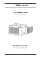
` Celair Profile Series Fresh Air Conditioning Installation Instructions Profile 500, 600, 750, 850
Installation Instructions Table of Contents 1. INTRODUCTION____________________________________________________ 3 1.1. Important Notes ____________________________________________________ 3 1.2. Dealer / Installer Responsibility ________________________________________ 3 1.2.1. 1.2.2. 1.2.3. 1.3. Training ____________________________________________________________ 3 Legal & Statutory obligations ____________________________________________ 3 Safety and O.H.&S.
Installation Instructions 1.0 Introduction 1. INTRODUCTION Please take the time to fully read this Installation manual. Failure to follow these instructions may result in injury to you and damage to the air conditioner or your customer’s property. Installation of this Celair Fresh Air Conditioner must conform to local building rules and regulations, electrical and plumbing codes, Environmental Protection Authority (EPA) regulations, and all applicable Australian Standards.
Installation Instructions 1.0 Introduction 1.2.3. Safety and O.H.&S. Requirements • It is the responsibility of the dealer / installer to insure the environment is safe for the installer to carry out the installation. A risk assessment should be carried out in conformance to state codes of practice. An industry guide to “safe Work at Heights” is available from Climate Technologies.
Installation Instructions 2.0 Unit Location 2. UNIT LOCATION 2.1 Unit Location Check List • EPA - A correct installed unit will perform to specification on sound pressure radiated noise. As an installer, you have a professional obligation to ensure that every practical and reasonable effort is made to install this product to best practice guidelines and ensures that any operational noise does not affect neighbours.
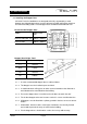
Installation Instructions 3.0 Unit Installation 3. UNIT INSTALLATION 3.1. Installing the Dropper Duct All Celair Fresh Air Conditioners are designed to be fully supported by a metal dropper duct. Metal dropper ducts must be designed, located and fixed to comply to the relevant building codes. Plastic dropper ducts are not recommended for use.
Installation Instructions 3.0 Unit Installation 3.2. Installing the Enviroseal Duct Shutter - Optional Accessory Step 1 The Enviroseal duct shutter must be installed a minimum of 150mm below the top of the dropper duct. If the dropper duct is fitted with insulation, remove insulation to give the shutter free operation. Step 2 Ensure the Enviroseal is secured horizontally on both angles.
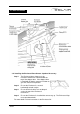
Installation Instructions 3.0 Unit Installation 3.3. Installing the Air Conditioner 3.3.1. Remove 4 Louvre panels from unit and place in a safe place to ensure no damage. To remove Louvre: STEP 1. Lift the Louvre assembly up approximately 15mm over the corner post location. STEP 2. Tilt the Louvre back from the top of unit and remove. 3.3.2. The venturi / fan assembly can be removed to assist in carrying the unit on the roof. To remove the fan / venturi assembly:- STEP 1.
Installation Instructions 3.0 Unit Installation NOTE: Handle the fan/venturi assembly with care, as the fan blade is not protected by the venturi once removed. 3.3.3. Store the fan / venturi assembly in a safe area until final installation to ensure no damage. Store the fan upside down (on the motor) ensuring no damage to the fan assembly. (Do not store in the gutter.
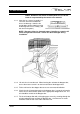
Installation Instructions 3.0 Unit Installation 3.3.8. Lift the fan deck onto the roof and reinstall into the unit. Ensure the venturi is correctly rotated for the motor wiring loom and has snapped into the location notches. Spin fan blade by hand to ensure that the blade does not touch the inlet ring. 3.3.9. Reconnect the fan loom to the control box. 3.3.10. Connect the 24-volt water solenoid cable to the control (where fitted). 3.3.11. Connect communication cables to the control box 3.3.12.
Installation Instructions 3.
Installation Instructions 4.0 Connections 4. CONNECTIONS All water connections must be carried out by a licensed plumber. A plumbing certificate of compliance is required. Correct water management in an evaporative air conditioner is vitally important to the operation and longevity of the product. If the water management is not set correctly by the installer to the local water condition, warranty will be void.
Installation Instructions 4.0 Connections • Unit water connection a ½” BSP female flexible connection. Use the flexible connector supplied for the connection between the isolating cock and the solenoid / float valve. NOTE: In areas where water pipes freeze, a low level drain tap or pressure expansion control valve provision will be needed to drain the water piping to prevent damage to the air conditioner. The customer should also be advised on its operation by the dealer / installer.
Installation Instructions 4.0 Connections 4.3.2. Fitting the Enviroflow Water Conservation System - Optional Accessory – (This does not replace the Overflow Fitting) The Enviroflow water conservation system uses water pressure to close the dump valve. There is a requirement for a minimum of 100kpa water pressure to maintain the dump valve mechanism closed. STEP 1 Remove nut from the dump valve.
Installation Instructions 4.0 Connections OPTION 1. A discharge point to a roof gutter pop outlet, providing the downpipe is not used for the collection of water for potable use. OPTION 2. Direct to downpipe via a tundish, providing the downpipe is not used for the collection of water for potable use. OPTION 3. A surface stormwater drainage system. Provided the surface is graded away from the building and ponding does not occur, and the discharge does not present a safety risk to pedestrians (eg.
Installation Instructions 4.0 Connections OPTION 4. A sanitary drainage system via a tundish in one of the following forms in accordance with AS/NZS 3500.2.2 - 1996 clause 4.6.7.8 & 11.22.
Installation Instructions 4.0 Connections OPTION 5. An absorption pit. Provided the following conditions can be met: • Only permitted where no sanitary or surface water drainage is available. • The pit can only be constructed in permeable ground • Of a size appropriate for the volume of discharge • Located so the discharge water will not cause damage to buildings by changing moisture conditions. OPTION 6. To a suitable water spreader.
Installation Instructions 4.0 Connections 4.4. Electrical 4.4.1. Wiring – Important Notes • A LICENSED ELECTRICIAN must carry out 240-volt connection wiring to the unit. It is the responsibility of the LICENSED ELECTRICIAN that the unit is connected as per AS3000 (Wiring rules) and any local regulations and statutory or legal requirements. A compliance certificate is required for any new electrical connections.
Installation Instructions 4.0 Connections • Drill a 50mm (2”) hole in the dropper to bring the service lead and controller cable into the ceiling space. The rubber grommet fitted to the service lead is used to seal the hole in the dropper from the inside. • Connect the controller and solenoid cables into the control box. Refer to Controller installation and commissioning instructions • • Plug the pre-wired service lead into the GPO.
Installation Instructions 5.0 Commissioning 5. COMMISSIONING 5.1. Water Levels 5.1.1. Turn water on to unit and allow unit to fill. The water should be 30 to 35mm from the top of the overflow. 5.1.2. If an Enviroflow Water Conservation System is fitted, turn the unit on and set the pre-cool function. This will activate the solenoid valve and allow time to check the float valve setting. 5.1.3. Adjusting the float valve arm: while the float valve arm is factory set some adjustment may be required.
Installation Instructions 5.0 Commissioning • With normal town water supply, bleed rate should be adjusted so that the discharge is not less than 10 litres per hour. Increased water hardness may require a higher bleed rate and increased maintenance. • It is recommended to plumb the bleed off hose through the overflow fitting and to waste as the discharge may cause unsightly stains.
Installation Instructions 5.0 Commissioning 5.7. Commissioning Check List You must complete, date and sign the ‘tick box’ checklist in the owner’s manual. Use this copy to check the installation prior to completing the owner’s documentation. Unit All equipment ordered by the customer is installed. The unit is level and secure. The tank is free of foreign matter and debris and the water isolating tap is turned ON. Water drainpipe work is completed and sealed.
Installation Instructions 5.0 Commissioning Ductwork and general The Enviroseal functions correctly with the shutters opening downwards at 90° All roof penetrations are fully sealed and watertight. All ductwork is completed to plan, correctly supported and airtight, with no bend less than 1.5 x the ductwork diameter. Air distribution checked, dampers are adjusted and all outlets correctly adjusted and wiped clean. Man hole cover replaced.
Manufactured by Climate Technologies ABN 13 001 418 042 26 Nylex Avenue Salisbury, SA 5108 Australia www.climatetechnologies.com.