Advanced Series Advanced Series GT INSTRUCTION MANUAL INTRODUCTION ...........................................................................................................................................................
Warning ...................................................................................................................................................... 4 ASSEMBLY.....................................................................................................................................................................7 Setting up the Tripod ..................................................................................................................................
Version.............................................................................................................................................. 27 Get Alt-Az......................................................................................................................................... 27 Goto Alt-Az ...................................................................................................................................... 27 Hibernate.................................................
Congratulations on your purchase of the Celestron Advanced Series telescope (AST)! The Advanced Series of telescopes come in standard (non-computerized) and computerized GT models. The Advanced Series is made of the highest quality materials to ensure stability and durability. All this adds up to a telescope that gives you a lifetime of pleasure with a minimal amount of maintenance. Furthermore, your Celestron telescope is versatile — it will grow as your interest grows.
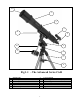
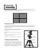
12 (C8-N Shown) 1 2 3 11 4 10 5 9 6 7 8 Fig 1-1 - The Advanced Series C6-R 1. 2. 3. 4. 5. 6. Optical Tube Tube Rings Finderscope Focuser / Eyepiece Equatorial Mount Latitude Adjustment Lever 7. 8. 9. 10. 11. 12.
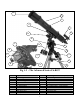
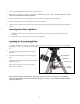
12 1 2 11 3 4 15 14 A 10 5 B 6 C 13 9 7 D E 8 Fig 1-2 - The Advanced Series C6-RGT 1. 2. 3. 4. 5. 6. 7. Optical Tube Tube Rings Finderscope Focuser / Eyepiece Equatorial Mount Latitude Adjustment Lever 2" Steel Tripod CONTROL PANEL 8. 9. 10. 11. 12. 13. 14. 15. Center Leg Brace / Accessory Tray Counterweights Counterweight Bar Dovetail Slide Bar Objective Lens Shade Hand Control R.A.
This section covers the assembly instructions for your Celestron Advanced Series Telescope (AST). Your AST telescope should be set up indoor the first time so that it is easy to identify the various parts and familiarize yourself with the correct assembly procedure before attempting it outdoor. 21019 / 21020 C6-R Diameter 150mm (6.0") refractor Focal Length 1200mm F/8 Eyepiece 20mm - 1.
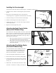
1. Locate the azimuth adjustment screws on the equatorial mount. 2. Retract the screws so they no longer extend into the azimuth housing on the mount. Do NOT remove the screws since they are needed later for polar alignment. 3. Hold the equatorial mount over the tripod head so that the azimuth housing is above the metal peg. 4. Place the equatorial mount on the tripod head so that the two are flush. 5.
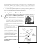
Installing the Counterweight The Advanced C6-R comes with two counterweights. To install the counterweight(s): 1. Orient the mount so that the counterweight bar points toward the ground . 2. Remove the counterweight safety screw on the end of the counterweight bar (i.e., opposite the end that attaches to the mount). 3. Loosen the locking screw on the side of the counterweight. 4. Slide the counterweight onto the shaft (see Figure 2-5). 5.
place. As mentioned above, there are two R.A. shafts, one on either side of the mount. It makes no difference which shaft you use since both work the same. Use whichever one you find more convenient. If, after a few observing sessions, you find the R.A. slow motion knob is more accessible from the other side, pull firmly to remove the knob, then install it on the opposite side. 5. The DEC slow motion knob attaches in the same manner as the R.A. knob.
Installing the Finderscope To install the finderscope onto the telescope you must first mount the finderscope through the finder bracket and then attach it to the telescope. Toward the rear of the telescope tube, near the focusing assembly, there is a small bracket with a set screw in it. This is where the finderscope bracket will be mounted. To install the finderscope: 1. Slide the rubber O-ring over the eyepiece end of the finderscope and roll it 2/3 of the way up the finderscope. 2.
Eyepieces are commonly referred to by focal length and barrel diameter. The focal length of each eyepiece is printed on the eyepiece barrel. The longer the focal length (i.e., the larger the number) the lower the eyepiece magnification (i.e., power) and the shorter the focal length (i.e., the smaller the number) the higher the magnification. Generally, you will use low-to-moderate power when viewing. For more information on how to determine power, see the section on “Calculating Magnification.
Figure 2-12 Figure 2-13 Like the R.A. balance, these are general balance instructions and will reduce undue stress on the mount. When taking astrophotographs, this balance process should be done for the specific area at which the telescope is pointing. Adjusting the Mount In order for a motor drive to track accurately, the telescope’s axis of rotation must be parallel to the Earth’s axis of rotation, a process known as polar alignment. Polar alignment is achieved NOT by moving the telescope in R.A.
latitude screw, first use the rear screw to raise the mount head all the way up. Then remove the front latitude screw completely. Now you should be able to manually move the mount head all the way to its lowest latitude. Now, using only the rear screw, raise the mount to your desired latitude. Adjusting the Mount in Azimuth For rough adjustments in azimuth, simply pick up the telescope and tripod and move it. For fine adjustments in azimuth: 1.
The Advanced Series GT, computerized version of each telescope has a hand controller designed to give you instant access to all the functions that your telescope has to offer. With automatic slewing to over 40,000 objects, and common sense menu descriptions, even a beginner can master its variety of features in just a few observing sessions. Below is a brief description of the individual components of the computerized hand controller: 1. 2. 3.
4. Catalog Keys: The Advanced Series has keys on the hand control to allow direct access to each of the catalogs in its database. The hand control contains the following catalogs in its database: Messier – Complete list of all Messier objects. NGC – Complete list of all the deep-sky objects in the Revised New General Catalog. Caldwell – A combination of the best NGC and IC objects. Planets - All 8 planets in our Solar System plus the Moon.
Alignment Procedures In order for the telescope to accurately point to objects in the sky, it must first be aligned to three known positions (stars) in the sky. With this information, the telescope can create a model of the sky, which it uses to locate any object with known coordinates.
4. Select one of the four alignment methods as described below. Note: If incorrect information is entered into the hand control, the UNDO button acts like a back space button allowing the user to re-enter the correct data. Auto Align Auto Align allows the telescope to automatically choose three stars (two on one side of the Meridian, and one on the opposite side) on which to align itself. To Auto Align your telescope: 1. Select Auto Align from the alignment choices given.
the eyepiece, pressing ENTER when complete. NOTE: Although the telescope allows the user to select the alignment stars, for best all-sky pointing accuracy it is still necessary to select two alignment stars on one side of the Meridian and the third star on the opposite side of the Meridian.
Object Catalog Selecting an Object Now that the telescope is properly aligned, you can choose an object from any of the catalogs in the telescope's extensive database. The hand control has a key (4) designated for each of the catalogs in its database. There are two ways to select objects from the database: scrolling through the named object lists and entering object numbers. Helpful Hint Pressing the LIST key on the hand control will access all objects in the database that have common names or types.
Tour Mode The Advanced Series telescopes include a tour feature which automatically allows the user to choose from a list of interesting objects based on the date and time in which you are observing. The automatic tour will display only those objects that are within your set filter limits (see Filter Limits in the Setup Procedures section of the manual). To activate the Tour mode, press the TOUR key (6) on the hand control.
1 2 3 4 5 = = = = = .5x 1x (sidereal) 4x 8x 16x 6 7 8 9 = 64x = .5º / sec = 2º / sec = 3º / sec Nine available slew speeds Setup Procedures The Advanced GT contains many user defined setup functions designed to give the user control over the telescope's many advanced features.
that is not included in the regular database. There are several ways to save an object to memory depending on what type of object it is: GoTo Object: To go to any of the user defined objects stored in the database, scroll down to either GoTo Sky Obj or Goto Land Obj and enter the number of the object you wish to select and press ENTER. The telescope will automatically retrieve and display the coordinates before slewing to the object.
Note: Some of the databases contain thousands of objects, and can therefore take several minutes to return the closest objects. Precise GoTo The Advanced Series telescopes have a precise goto function that can assist in finding extremely faint objects and centering objects closer to the center of the field of view for astrophotography and CCD imaging. Precise Goto automatically searches out the closest bright star to the desired object and asks the user to carefully center it in the eyepiece.
example, if you are observing from a mountainous location where the horizon is partially obscured, you can set your minimum altitude limit to read +20º. This will make sure that the hand control only displays objects that are higher in altitude than 20º. Observing Tip! If you want to explore the entire object database, set the maximum altitude limit to 90º and the minimum limit to – 90º. This will display every object in the database lists regardless of whether it is visible in the sky from your location.
in R.A. (azimuth) until it reaches the point that the cables are extended to their maximum. Then by displaying the telescopes azimuth in this position (by looking at Get Alt-Az under the Utilities menu) you can determine the telescopes azimuth at its most extended position. Enter this azimuth reading for either the maximum or minimum azimuth slew limit to ensure that the telescope will not slew beyond this point.
should be. Use the equatorial head latitude and azimuth adjustments to place Polaris in the center of the eyepiece. Do not use the direction buttons to position Polaris. Once Polaris is centered in the eyepiece press ENTER; the polar axis should then be pointed towards the North Celestial Pole. Light Control – This feature allows you to turn off both the red key pad light and LCD display for daytime use to conserve power and to help preserve your night vision.
ADVANCED GT MENU TRACKING MODE EQ NORTH EQ SOUTH OFF RATE SIDEREAL SOLAR LUNAR VIEW TIME-SITE SCOPE SETUP SETUP TIME-SITE ANTI-BACKLASH FILTER LIMITS DIRECTION BUTTONS GOTO APPROACH AUTOGUIDE RATE AZIMUTH LIMITS EAST/WEST FILTERING UTILITIES CALIBRATE GOTO HOME POSITION POLAR ALIGN LIGHT CONTROL FACTORY SETTING VERSION GET ALT-AZ GOTO ALT-AZ HIBERNATE TURN ON/OFF GPS USER OBJECTS ALIGNMENT LIST START-UP PROCUDURE SET TO INDEX ENTER TIME DLS/ST TIME ZONE ENTER DATE- MM/DD/YY ENTER LONG/LAT AUTO ALIGN CENT
A telescope is an instrument that collects and focuses light. The nature of the optical design determines how the light is focused. Some telescopes, known as refractors, use lenses. Other telescopes, known as reflectors, use mirrors. Developed in the early 1600s, the refractor is the oldest telescope design. It derives its name from the method it uses to focus incoming light rays. The refractor uses a lens to bend or refract incoming light rays, hence the name (see Figure 4-1).
Focusing To focus your telescope, simply turn the focus knob located directly below the focuser. Turning the knob clockwise allows you to focus on an object that is farther than the one you are currently observing. Turning the knob counterclockwise from you allows you to focus on an object closer than the one you are currently observing. • If you wear corrective lenses (specifically glasses), you may want to remove them when observing with an eyepiece attached to the telescope.
Although the power is variable, each instrument under average skies has a limit to the highest useful magnification. The general rule is that 60 power can be used for every inch of aperture. For example, the C6-R is 6 inches in diameter. Multiplying 6 by 60 gives a maximum useful magnification of 360 power. Although this is the maximum useful magnification, most observing is done in the range of 20 to 35 power for every inch of aperture which is 120 to 210 times for the C6-R telescope.
Up to this point, this manual covered the assembly and basic operation of your telescope. However, to understand your telescope more thoroughly, you need to know a little about the night sky. This section deals with observational astronomy in general and includes information on the night sky and polar alignment. The Celestial Coordinate System To help find objects in the sky, astronomers use a celestial coordinate system that is similar to our geographical coordinate system here on Earth.
Motion of the Stars The daily motion of the Sun across the sky is familiar to even the most casual observer. This daily trek is not the Sun moving as early astronomers thought, but the result of the Earth's rotation. The Earth's rotation also causes the stars to do the same, scribing out a large circle as the Earth completes one rotation. The size of the circular path a star follows depends on where it is in the sky.
Latitude Scales The easiest way to polar align a telescope is with a latitude scale. Unlike other methods that require you to find the celestial pole by identifying certain stars near it, this method works off of a known constant to determine how high the polar axis should be pointed. The Advanced Series mount can be adjusted from 30 to 60 degrees (see figure 5-3).
Remember, while Polar aligning, do NOT move the telescope in R.A. or DEC. You do not want to move the telescope itself, but the polar axis. The telescope is used simply to see where the polar axis is pointing. Like the previous method, this gets you close to the pole but not directly on it. The following methods help improve your accuracy for more serious observations and photography.
Declination Drift Method of Polar Alignment This method of polar alignment allows you to get the most accurate alignment on the celestial pole and is required if you want to do long exposure deep-sky astrophotography through the telescope. The declination drift method requires that you monitor the drift of selected stars. The drift of each star tells you how far away the polar axis is pointing from the true celestial pole and in what direction.
With your telescope set up, you are ready to use it for observing. This section covers visual observing hints for both solar system and deep sky objects as well as general observing conditions which will affect your ability to observe. Observing the Moon Often, it is tempting to look at the Moon when it is full. At this time, the face we see is fully illuminated and its light can be overpowering. In addition, little or no contrast can be seen during this phase.
For safe solar viewing, use a solar filter that reduces the intensity of the Sun's light, making it safe to view. With a filter you can see sunspots as they move across the solar disk and faculae, which are bright patches seen near the Sun's edge. Solar Observing Hints • The best time to observe the Sun is in the early morning or late afternoon when the air is cooler. • To center the Sun without looking into the eyepiece, watch the shadow of the telescope tube until it forms a circular shadow.
disturbances vary from time-to-time and place-to-place. The size of the air parcels compared to your aperture determines the "seeing" quality. Under good seeing conditions, fine detail is visible on the brighter planets like Jupiter and Mars, and stars are pinpoint images. Under poor seeing conditions, images are blurred and stars appear as blobs. The conditions described here apply to both visual and photographic observations. Figure 6-1 Seeing conditions directly affect image quality.
After looking at the night sky for a while you may want to try photographing it. Several forms of photography are possible with your telescope, including terrestrial and celestial photography. Both of these are discussed in moderate detail with enough information to get you started. Topics include the accessories required and some simple techniques. More information is available in some of the publications listed at the end of this manual.
5. Locate the area of the sky that you want to photograph and move the telescope so that it points in that direction. 6. Find a suitable guide star in the telescope eyepiece field of view. This is relatively easy since you can search a wide area without affecting the area covered by your camera lens. If you do not have an illuminated cross hair eyepiece for guiding, simply defocus your guide star until it fills most of the field of view. This makes it easy to detect any drift. 7.
Lunar Phase Crescent Quarter Full ISO 50 1/2 1/15 1/30 ISO 100 1/4 1/30 1/60 ISO 200 1/8 1/60 1/125 ISO 400 1/15 1/125 1/250 Table 7-1 Above is a listing of recommended exposure times when photographing the Moon at the prime focus of your telescope. The exposure times listed in table 7-1 should be used as a starting point. Always make exposures that are longer and shorter than the recommended time. Also, take a few photos at each shutter speed. This will ensure that you will get a good photo.
Auto Guiding The Advanced GT telescope has a designated auto guiding port for use with a CCD autoguider. The diagram below may be useful when connecting the CCD camera cable to the telescope and calibrating the autoguider. Note that the four outputs are active-low, with internal pull-ups and are capable of sinking 25 mA DC.
While your telescope requires little maintenance, there are a few things to remember that will ensure your telescope performs at its best. Care and Cleaning of the Optics Occasionally, dust and/or moisture may build up on the objective lens of your telescope. Special care should be taken when cleaning any instrument so as not to damage the optics. If dust has built up on the lens, remove it with a brush (made of camel’s hair) or a can of pressurized air.
sit outside for 15 to 30 minutes before attempting collimation. You should also wait for a night with good seeing conditions and avoid looking over anything that produces heat waves (i.e., roof tops, car hoods, etc.). Pick a bright star and center it in the field of the telescope. Study the image of the star while racking it in and out of focus using an eyepiece that yields 30 to 60 power for every inch of aperture. If an unsymmetrical focus pattern is present, then collimation is necessary.
You will find that additional accessories enhance your viewing pleasure and expand the usefulness of your telescope. For ease of reference, all the accessories are listed in alphabetical order. Adapter AC (#18773) - Allow DC (battery powered) telescopes to be converted for use with 120 volt AC power. Auxiliary Port Accessory (#93965) – This accessory plugs into the auxiliary port of the telescopes control panel to provide additional ports for accessories like the CN-16 GPS as well as a PC programming port.
Series 3 – #94119-30 Light Red, Blue, Green, ND50% T (#s 23A, 38A, 58, 96ND-50) Series 4 – #94119-40 Yellow, Deep Yellow, Violet, Pale Blue (#s 8, 47, 82A, 96ND-13) Flashlight, Night Vision - (#93588) - Celestron’s premium model for astronomy, using two red LED's to preserve night vision better than red filters or other devices. Brightness is adjustable. Operates on a single 9 volt battery (included).
RS-232 Cable (#93920) – Allows your Advanced Series telescope to be controlled using a laptop computer or PC. Once connected, the telescope can be controlled using popular astronomy software programs. Sky Maps (#93722) - Celestron Sky Maps are the ideal teaching guide for learning the night sky. You wouldn’t set off on a road trip without a road map, and you don’t need to try to navigate the night sky without a map either.
Appendix A – Technical Specifications Advanced Series 21019 / 21020 Specifications: 150mm (6.0") refractor 1200mm F/8 9x50 CG-5 Equatorial 20mm – 1.
Appendix B - Glossary of Terms AAbsolute magnitude Airy disk Alt-Azimuth Mounting Altitude Aperture Apparent Magnitude Arcminute Arcsecond Asterism Asteroid Astrology Astronomical unit (AU) Aurora Azimuth BBinary Stars CCelestial Equator Celestial pole Celestial Sphere Collimation DDeclination (DEC) EEcliptic Equatorial mount FFocal length The apparent magnitude that a star would have if it were observed from a standard distance of 10 parsecs, or 32.6 light-years. The absolute magnitude of the Sun is 4.
JJovian Planets KKuiper Belt LLight-Year (LY) MMagnitude Meridian Messier NNebula North Celestial Pole Nova OOpen Cluster PParallax Parfocal Parsec Point Source RReflector Resolution Right Ascension: (RA) SSchmidt Telescope Sidereal Rate Any of the four gas giant planets that are at a greater distance form the sun than the terrestrial planets. A region beyond the orbit of Neptune extending to about 1000 AU which is a source of many short period comets.
telescope at this rate. The rate is 15 arc seconds per second or 15 degrees per hour. TTerminator UUniverse VVariable Star WWaning Moon The boundary line between the light and dark portion of the moon or a planet. The totality of astronomical things, events, relations and energies capable of being described objectively. A star whose brightness varies over time due to either inherent properties of the star or something eclipsing or obscuring the brightness of the star.
APPENDIX C LONGITUDES AND LATITUDES LONGITUDE degrees min ALABAMA Anniston Auburn Birmingham Centreville Dothan Fort Rucker Gadsden Huntsville Maxwell AFB Mobile Mobile Aeros Montgomery Muscle Shoal Selma Troy Tuscaloosa ALASKA Anchorage Barrow Fairbanks Haines Hrbor Homer Juneau Ketchikan Kodiak Nome Sitka Sitkinak Skagway Valdez ARIZONA Davis-M AFB Deer Valley Douglas Falcon Fld Flagstaff Fort Huachuc Gila Bend Goodyear GrandCanyon Kingman Luke Page Payson Phoenix Prescott Safford Awrs Scottsdale Show Low
Melbourne Miami Naples Nasa Shuttle Orlando Panama City Patrick AFB Pensacola Ruskin Saint Peters Sanford Sarasota Tallahassee Tampa Intl Titusville Tyndall AFB Vero Beach West Palm Beach Whiting Fld GEORGIA Albany Alma Athens Atlanta Augusta/Bush Brunswick Columbus Dobbins AFB Fort Benning Ft Stewart Hunter Aaf La Grange Macon/Lewis Moody AFB Robins AFB Rome/Russell Valdosta Waycross HAWAII Barbers Pt Barking San Fr Frigate Hilo Honolulu Int Kahului Maui Kaneohe Mca Kilauea Pt Lanai-Lanai Lihue-Kauai Maui
Wurtsmith Ypsilanti MINNESOTA Albert Lea Alexandria Bemidji Muni Brainerd-Crw Detroit Laks Duluth Ely Fairmont Fergus Falls Grand Rapids Hibbing Intl Falls Litchfield Mankato Marshall Arpt Minneapolis Park Rapids Pequot Lake Rochester Saint Paul St Cloud Thief River Tofte Warroad Worthington MISSISSIPPI Columbus AFB Golden Trian Greenville Greenwood Gulfport Hattiesburg Jackson Keesler AFB Laurel Mccomb Meridian NAS Meridian/Key Natchez Oxford Tupelo MISSOURI Columbia Cape Girardeau Ft Leonard Jefferson Cit
LONGITUDE degrees OKLAHOMA Altus AFB 99 Ardmore 97 Bartlesville 96 Clinton 99 Enid 97 Fort Sill 98 Gage 99 Hobart 99 Lawton 98 Mcalester 95 Norman 97 Oklahoma 97 Page 94 Ponca City 97 Stillwater 97 Tinker AFB 97 Tulsa 95 Vance AFB 97 OREGON Astoria 123 Aurora 122 Baker 117 Brookings 124 Burns Arpt 118 Cape Blanco 124 Cascade 121 Corvallis 123 Eugene 123 Hillsboro 122 Klamath Fall 121 La Grande 118 Lake View 120 Meacham 118 Medford 122 Newport 124 North Bend 124 Ontario 117 Pendleton 118 Portland 122 Redmond
LONGITUDE LATITUDE degrees min degrees Walla Walla 118 16.8 46 Wenatchee 120 1.2 47 Whidbey Is 122 39 48 Yakima 120 31.8 46 WEST VIRGINIA Beckley 81 7.2 37 Bluefield 81 13.2 37 Charleston 81 3.6 38 Clarksburg 80 13.8 39 Elkins 79 51 38 Huntington 82 33 38 Lewisburg 80 2.4 37 Martinsburg 77 58.8 39 Morgantown 79 55.2 39 Parkersburg 81 25.8 39 Wheeling 80 39 40 Wh Sulphur 80 1.2 37 LONGITUDE degrees min min 6 24 21 34.
Appendix D - RS-232 Connection You can control your telescope with a computer via the RS-232 port on the computerized hand control and using an optional RS-232 cable (#93920). Once connected, the telescope can be controlled using popular astronomy software programs. Communication Protocol: The Advanced GT communicates at 9600 bits/sec, No parity and a stop bit. All angles are communicated with 16 bit angle and communicated using ASCII hexadecimal.
Additional RS232 Commands Send Any Track Rate Through RS232 To The Hand Control 1. 2. 3. 4. Multiply the desired tracking rate (arcseconds/second) by 4. Example: if the desired trackrate is 150 arcseconds/second, then TRACKRATE = 600 Separate TRACKRATE into two bytes, such that (TRACKRATE = TrackRateHigh*256 + rackRateLow). Example: TrackRateHigh = 2 TrackRateLow = 88 To send a tracking rate, send the following 8 bytes: a. Positive Azm tracking: 80, 3, 16, 6, TrackRateHigh, TrackRateLow, 0, 0 b.
APPENDIX E – MAPS OF TIME ZONES 60
3 67
CELESTRON TWO YEAR WARRANTY A. Celestron warrants this telescope to be free from defects in materials and workmanship for two years. Celestron will repair or replace such product or part thereof which, upon inspection by Celestron, is found to be defective in materials or workmanship. As a condition to the obligation of Celestron to repair or replace such product, the product must be returned to Celestron together with proof-of-purchase satisfactory to Celestron. B.
Celestron 2835 Columbia Street Torrance, CA 90503 U.S.A. Tel. (310) 328-9560 Fax. (310) 212-5835 Web site at http//www.celestron.com Copyright 2003 Celestron All rights reserved. (Products or instructions may change without notice or obligation.) Item # 21019-INST Printed in China $10.