CGE Pro Series INSTRUCTION MANUAL CGE Pro 925 ● CGE Pro 1100 ● CGE Pro 1400
INTRODUCTION ........................................................................................................................................................................................................................................................ 4 Warning.................................................................................................................................................................................................................................... 4 ASSEMBLY.
Goto Axis Position .......................................................................................................................................................................................................30 Hibernate ...................................................................................................................................................................................................................... 30 Sun Menu ......................................................
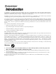
Congratulations on your purchase of the Celestron CGE Pro Series telescope! The CGE Pro Series is made of the highest quality materials to ensure stability and durability. All this adds up to a telescope that gives you a lifetime of pleasure with a minimal amount of maintenance. Furthermore, your Celestron telescope is versatile — it will grow as your interest grows. The CGE Pro Series ushers in the next generation of computer automated telescopes.
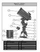
AS Figure 2.
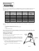
This section covers the assembly instructions for your Celestron Telescope. Your telescope should be set up indoor the first time so that it is easy to identify the various parts and familiarize yourself with the correct assembly procedure before attempting it outdoor. Diameter Focal Length Eyepiece Finderscope Diagonal Fastar Compat. Mount Tripod Software Counterweights #11086 CGE Pro 925 #11087 CGE Pro 1100 #11088 CGE Pro 1400 #11089 CGE Pro 1400 Fastar 235mm (9.
3. Slide the center portion of the tripod leg away from the tripod head until it is at the desired height. 4. Tighten the levers on each leg clamp to hold the legs in place. 5. Once that it is fully assembled, rotate the tripod so that one of the legs is pointing roughly towards north. Attaching the Accessory Tray 1. 2. Slide the accessory tray over the central rod so that the three cup indents are pushing against the inside of the tripod legs.
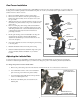
One Person Installation As an alternative to the method described above, The CGE Pro mount can be more easily assembled by one person if the polar housing axis is installed separately from the latitude side plates. To do this you must first lay the equatorial head on a flat soft surface and remove the two sections. 1. 2. 3. 4. 5. Remove the latitude indicator from the polar housing.
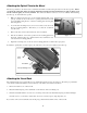
Attaching the Motor Cables 1. Locate the two motor cables. The longer cable attaches to the DEC motor while the shorted cable attaches to the RA motor. 2. Insert one end of each cable into the designated port on the electronic pier. See figure 2-5. DEC Motor 3. Attach the other end of the longer cable to the port on the side of the DEC motor and the shorter cable into the port on the RA motor. 4. Thread the cable ring onto each port to hold the cable securely in place.
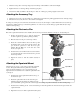
Attaching the Optical Tube to the Mount The telescope attaches to the mount via a dovetail slide bar which is mounted along the bottom of the telescope tube. Before you attach the optical tube, make sure that the declination and right ascension clutch knobs are tight (see Figure 2-14) and the counterweight(s) are securely installed. This will ensure that the mount does not move suddenly while attaching the telescope. To mount the telescope tube: 1.
Installing the Star Diagonal The star diagonal is a prism that diverts the light at a right angle to the light path of the telescope. This allows you to observe in positions that are physically more comfortable than if you looked Eyepiece straight through. To attach the star diagonal onto the optical tube: 1. Turn the set screw on the visual back until its tip no longer extends into (i.e., obstructs) the inner diameter of the visual back. 2.
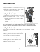
To install the finderscope: 1. Attach the bracket to the optical tube. To do this, place the curved portion of the bracket with the slot over the two holes in the rear cell. Start threading the screws in by hand and tighten fully with an Allen wrench. 2. Partially thread-in the three nylon thumbscrews that hold the finder in place inside the bracket. Tighten the screws until the nylon heads are flush with the inner diameter of the bracket ring.
2. Slide the eyepiece end of the finderscope into the front ring of the bracket (the front ring is the one without the adjustment screws), then through the back ring. It may be necessary to push down the spring loaded pivot screw so that the finder will pass through the back ring (see figure 2-12) 3. Push the finder back until the O-Ring is snug inside the front ring of the finder bracket. 4. Hand tighten the two alignment thumb screws until they make contact with the finderscope.
Balancing the Mount in R.A. To eliminate undue stress on the mount, the telescope should be properly balanced around the polar axis. Proper balancing is crucial for accurate tracking. To balance the mount: 1. Verify that the telescope is securely attached to the telescope mounting platform. 2. Loosen the R.A. locking knobs and position the telescope off to one side of the mount. The counterweight bar will extend horizontally on the opposite side of the mount. 3.
6. Slightly loosen the knobs that holds the telescope to the mounting platform and slide the telescope either forward or backward until it remains stationary when the DEC clutch is loose. Do NOT let go of the telescope tube while the knob on the mounting platform is loose. 7. Tighten the knobs on the telescope mounting platform to hold the telescope in place. Like R.A. balance, these are general balance instructions and will reduce undue stress on the mount.
Attaching the Hand Control Holder The telescope comes with a hand control holder to place the computerized hand control. The hand control holder comes attached to the tripod leg and can be easily removed for convenient use. Hand Control Holder Powering the Telescope The telescope mount can be powered by the supplied car battery adapter or optional 12v AC adapter. Use only adapters supplied by Celestron.
All Celestron computerized telescope come with a hand control designed to give you instant access to all the functions that your telescope has to offer. With automatic slewing to over 40,000 objects, and common sense menu descriptions, even a beginner can master its variety of features in just a few observing sessions. Below is a brief description of the individual components of the computerized hand controller: 1. 2. 3.
4. Catalog Keys: The hand control has keys on the hand control to allow direct access to each of the catalogs in its database. The hand control contains the following catalogs in its database: Messier – Complete list of all Messier objects. NGC – Complete list of all the deep-sky objects in the Revised New General Catalog. Caldwell – A combination of the best NGC and IC objects. Planets - All 8 planets in our Solar System plus the Moon. Stars – A compiled list of the brightest stars from the SAO catalog.
the telescope will automatically slew to. One Star Align uses the same time/location information but only uses one star for alignment. Solar System Align will display a list of visible daytime objects (planets and the moon) available to align the telescope. Quick-Align will ask you to input all the same information as you would for the Auto Align procedure.
Select one of the alignment methods as described below. Note: If incorrect information is entered into the hand control, the UNDO button acts like a back space button allowing the user to re-enter the correct data. Two Star Align Two-Star Align allows the user to select two stars on which to align the telescope. To align your telescope using the Two-Star Align method: 1. Select Two-Star Align from the alignment choices given.
Solar System Align Solar System Align is designed to provide excellent tracking and GoTo performance by using solar system objects (Sun, Moon and planets) to align the telescope with the sky. Solar System Align is a great way to align your telescope for daytime viewing as well as a quick way to align the telescope for nighttime observing. Never look directly at the sun with the naked eye or with a telescope (unless you have the proper solar filter). Permanent and irreversible eye damage may result.
NOTE: Just like with Quick-Align, you can use the Re-alignment feature (see below) to improve your telescopes pointing accuracy after using the Last Alignment method. To maintain a more accurate alignment over a series of observing sessions, use the Hibernate feature described later in this chapter. Re-Alignment The telescopes has a re-alignment feature which allows you to replace any of the original alignment stars with a new star or celestial object.
Slewing to an Object Once the desired object is displayed on the hand control screen, choose from the following options: Press the INFO Key. This will give you useful information about the selected object such as R.A. and declination, magnitude size and text information for many of the most popular objects. Press the ENTER Key. This will automatically slew the telescope to the coordinates of the object. Caution: Never slew the telescope when someone is looking into the eyepiece.
Rate Button Pressing the RATE key (11) allows you to instantly change the speed rate of the motors from high speed slew rate to precise guiding rate or anywhere in between. Each rate corresponds to a number on the hand controller key pad. The number 9 is the fastest rate (3º per second, depending on power source) and is used for slewing between objects and locating alignment stars. The number 1 on the hand control is the slowest rate (.
Sidereal This rate compensates for the rotation of the Earth by moving the telescope at the same rate as the rotation of the Earth, but in the opposite direction. When the telescope is polar aligned, this can be accomplished by moving the telescope in right ascension only. Lunar Used for tracking the moon when observing the lunar landscape. Solar Used for tracking the Sun when solar observing with the proper filter.
Goto R.A/ Dec - Allows you to input a specific R.A. and declination and slew to it. To store a set of coordinates (R.A./Dec) permanently into the database, save it as a User Defined Object as described above. Helpful Hint Identify Identify Mode will search any of the telescope's database catalogs or lists and display the name and offset distances to the nearest matching objects. This feature can serve two purposes. First, it can be used to identify an unknown object in the field of view of your eyepiece.
by inputting a value which quickly rewinds the motors just enough to eliminate the play between gears. The amount of compensation needed depends on the slewing rate selected; the slower the slewing rate the longer it will take for the star to appear to move in the eyepiece. There are two values for each axis, positive and negative: Positive is the amount of compensation applied when you press the button, in order to get the gears moving quickly without a long pause.
Autoguide Rate – Allows the user to set an autoguide rate as a percentage of sidereal rate. This is helpful when calibrating your telescope to a CCD autoguider for long exposure photography. OTA Orientation- Some users may wish to use an optional tandem bar adapter which allows you to attach to the mount two optical tubes at the same time. When most tandem bars are attached to a mount, the optical tubes are positioned at a 90 degree angle from the standard configuration.
adjust the slew limit on the side of the mount that is restricted by the cables, and command the mount the stop slewing before it reaches this point. Or if you are taking an image of an object that has just crossed the Meridian, you can set the limit to allow the mount to continue tracking in the same direction past the Meridian without the need to "flip" the telescope around to the opposite side of the mount (see Meridian feature above).
R.A. switch - this procedure records the offset error when the right ascension index switch is found at start-up. Calibrating the R.A. Index will improve the accuracy of your initial star alignments when aligning the telescope in the future. GoTo Calibration – Goto Calibration is a useful tool when attaching heavy visual or photographic accessories to the telescope.
Scrolling Menu This menus allows you to change the rate of speed that the text scrolls across the hand control display. Press the Up (number 6) button to increase the speed of the text. Press the Down (number 9) button to decrease the speed of the text. Set Mount Position The Set Mount Position menu can be used to maintain your alignment in cases where you wish to disengaged the clutches or similar situation.
LIST ALIGN MENU NAME STAR TRACKING NGC ALIGNMENT STARS MODE EQ NORTH SAO EQ SOUTH CALIB. STARS SOLAR SYSTEM RATE TOUR SIDEREAL POLAR ALIGN VARIABLE STARS SOLAR LUNAR ALIGN MOUNT ABELL VIEW TIME-SITE ASTERISM SCOPE SETUP DISPLAY ALIGN SETUP TIME-SITE ANTI-BACKLASH CALDWELL CCD OBJECTS FILTER LIMITS SYNC CONSTELLATIONS DIRECTION BUTTONS DOUBLE STARS GOTO APPROACH UNDO SYNC AUTOGUIDE RATES IC OTA ORIENTATION MESSIER MERIDIAN MOUNT SETTINGS ALIGNMENT NAMED OBJECT R.A.
A telescope is an instrument that collects and focuses light. The nature of the optical design determines how the light is focused. Some telescopes, known as refractors, use lenses. Other telescopes, known as reflectors, use mirrors. The SchmidtCassegrain optical system (or Schmidt-Cass for short) uses a combination of mirrors and lenses and is referred to as a compound or catadioptric telescope.
Focusing The Schmidt-Cassegrain focusing mechanism controls the primary mirror which is mounted on a ring that slides back and forth on the primary baffle tube. The focusing knob, which moves the primary mirror, is on the rear cell of the telescope just below the star diagonal and eyepiece. Turn the focusing knob until the image is sharp. If the knob will not turn, it has reached the end of its travel on the focusing mechanism. Turn the knob in the opposite direction until the image is sharp.
thousand yards. The apparent field of each eyepiece that Celestron manufactures is found in the Celestron Accessory Catalog (#93685). General Observing Hints When working with any optical instrument, there are a few things to remember to ensure you get the best possible image. Never look through window glass. Glass found in household windows is optically imperfect, and as a result, may vary in thickness from one part of a window to the next.
Up to this point, this manual covered the assembly and basic operation of your telescope. However, to understand your telescope more thoroughly, you need to know a little about the night sky. This section deals with observational astronomy in general and includes information on the night sky and polar alignment. The Celestial Coordinate System To help find objects in the sky, astronomers use a celestial coordinate system that is similar to our geographical coordinate system here on Earth.
Motion of the Stars The daily motion of the Sun across the sky is familiar to even the most casual observer. This daily trek is not the Sun moving as early astronomers thought, but the result of the Earth's rotation. The Earth's rotation also causes the stars to do the same, scribing out a large circle as the Earth completes one rotation. The size of the circular path a star follows depends on where it is in the sky.
Finding the North Celestial Pole In each hemisphere, there is a point in the sky around which all the other stars appear to rotate. These points are called the celestial poles and are named for the hemisphere in which they reside. For example, in the northern hemisphere all stars move around the north celestial pole. When the telescope's polar axis is pointed at the celestial pole, it is parallel to the Earth's rotational axis.
If you are observing from Los Angeles, which has a latitude of 34°, then the celestial pole is 34° above the northern horizon. All a latitude scale does then is to point the polar axis of the telescope at the right elevation above the northern (or southern) horizon. To align your telescope: 1. Make sure the polar axis of the mount is pointing due north. Use a landmark that you know faces north. 2. Level the tripod. There is a bubble level built into the mount for this purpose. 3.
To re-align your telescope: 2. 3. 4. 5. 6. Slew the telescope to one of the original alignment stars, or another bright star if the original alignment stars are no longer in a convenient location. Press the Align button and use the Up/Down buttons on the hand controller to select Alignment Stars from the list. The hand control will ask you which of the original alignment stars you wish to replace. Use the Up/Down buttons to select the desired star and press Enter.
With your telescope set up, you are ready to use it for observing. This section covers visual observing hints for both solar system and deep sky objects as well as general observing conditions which will affect your ability to observe. Observing the Moon Often, it is tempting to look at the Moon when it is full. At this time, the face we see is fully illuminated and its light can be overpowering. In addition, little or no contrast can be seen during this phase.
Solar Observing Hints The best time to observe the Sun is in the early morning or late afternoon when the air is cooler. To center the Sun without looking into the eyepiece, watch the shadow of the telescope tube until it forms a circular shadow. To ensure accurate tracking, be sure to select the solar tracking rate. Observing Deep Sky Objects Deep-sky objects are simply those objects outside the boundaries of our solar system.
Figure 6-1 Seeing conditions directly affect image quality. These drawings represent a point source (i.e., star) under bad seeing conditions (left) to excellent conditions (right). Most often, seeing conditions produce images that lie some where between these two extremes.
After looking at the night sky for a while you may want to try photographing it. Several forms of celestial photography are possible with your telescope, including short exposure prime focus, eyepiece projection, long exposure deep sky, terrestrial and even CCD imaging. Each of these is discussed in moderate detail with enough information to get you started. Topics include the accessories required and some simple techniques.
1. Load your camera with film that has a moderate-to-fast speed (i.e., ISO rating). Faster films are more desirable when the Moon is a crescent. When the Moon is near full, and at its brightest, slower films are more desirable. Here are some film recommendations: T-Max 100 T-Max 400 Any 100 to 400 ISO color slide film Fuji Super HG 400 Ektar 25 or 100 2. Center the Moon in the field of your telescope. 3. Focus the telescope by turning the focus knob until the image is sharp. 4.
Because of the high magnifications during eyepiece projection, the field of view is quite small which makes it difficult to find and center objects. To make the job a little easier, align the finder as accurately as possible. This allows you to get the object in the telescope's field based on the finder's view alone. Another problem introduced by the high magnification is vibration. Simply tripping the shutter even with a cable release produces enough vibration to smear the image.
Once you have mastered the technique, experiment with different films, different focal length eyepieces, and even different filters. Long Exposure Prime Focus Photography This is the last form of celestial photography to be attempted after others have been mastered. It is intended primarily for deep sky objects, that is objects outside our solar system which includes star clusters, nebulae, and galaxies. While it may seem that high magnification is required for these objects, just the opposite is true.
Periodic Error Correction (PEC) PEC for short, is a system that improves the tracking accuracy of the drive by reducing the number of user corrections needed to keep a guide star centered in the eyepiece. PEC is designed to improve photographic quality by reducing the amplitude of the worm errors. Using the PEC function is a three-step process. First, the CGE Pro needs to know the current position of its worm gear so that it has a reference when playing back the recorded error.
Does the PEC function make unguided astrophotography possible? Yes and no. For solar (filtered), lunar, and piggyback (up to 200mm), the answer is yes. However, even with PEC, off-axis guiding is still mandatory for long exposure, deep sky astrophotography. The optional Reducer/Corrector lens reduces exposure times making the task of guiding a little easier. Terrestrial Photography Your telescope makes an excellent telephoto lens for terrestrial (land) photography.
Focal Length & Speed Telescope Model Standard Cassegrain f/10 With Reducer/Corrector f/6.3 C8 80" (2032mm) 50.4" (1280mm) C9.25 93" (2350mm) 58" (1481mm) C11 110" (2800mm) 69" (1764mm) C14 154" (3910mm) 98" (2488mm) Table 7-3 Auto Guiding The CGE PRO mount has a designated auto guiding port for use with a CCD autoguider. The diagram below may be useful when connecting the CCD camera cable to the telescope and calibrating the autoguider.
While your telescope requires little maintenance, there are a few things to remember that will ensure your telescope performs at its best. Care and Cleaning of the Optics Occasionally, dust and/or moisture may build up on the corrector plate of your telescope. Special care should be taken when cleaning any instrument so as not to damage the optics. If dust has built up on the corrector plate, remove it with a brush (made of camel’s hair) or a can of pressurized air.
Before you begin the collimation process, be sure that your telescope is in thermal equilibrium with the surroundings. Allow 45 minutes for the telescope to reach equilibrium if you move it between large temperature extremes. To verify collimation, view a star near the zenith. Use a medium to high power ocular — 12mm to 6mm focal length. It is important to center a star in the center of the field to judge collimation. Slowly cross in and out of focus and judge the symmetry of the star.
7. Once the star image is in the center of the field of view, check to see if the rings are concentric. If the central obstruction is still skewed in the same direction, then continue turning the screw(s) in the same direction. If you find that the ring pattern is skewed in a different direction, than simply repeat steps 2 through 6 as described above for the new direction. Perfect collimation will yield a star image very symmetrical just inside and outside of focus.
You will find that additional accessories enhance your viewing pleasure and expand the usefulness of your telescope. For ease of reference, all the accessories are listed in alphabetical order. AC Adapter (#18779) – 2.5amp, AC adapter for use with the CGEM and CGE Pro telescopes. Barlow Lens - A Barlow lens is a negative lens that increases the focal length of a telescope. Used with any eyepiece, it doubles the magnification of that eyepiece. Celestron offers two Barlow lens in the 1-1/4" size.
Series 1 – #94119-10 Orange, Light Blue, ND13%T, Polarizing (#s 21, 80A, #15, Polarizing) Series 2 – #94119-20 Deep Yellow, Red, Light Green, ND25% T (#s 12, 25, 56, 96ND-25) Series 3 – #94119-30 Light Red, Blue, Green, ND50% T (#s 23A, 38A, 58, 96ND-50) Series 4 – #94119-40 Yellow, Deep Yellow, Violet, Pale Blue (#s 8, 47, 82A, ND96-13) Flashlight, Night Vision - (#93588) - Celestron’s premium model for astronomy, using two red LED's to preserve night vision better than red filters or other devices.
film. It also increases the field of view significantly and is ideal for wide-field, deep-space viewing. It is also perfect for beginning prime focus, long-exposure astro photography when used with the radial guider. It makes guiding easier and exposures much shorter. Sky Maps (#93722) - Celestron Sky Maps are the ideal teaching guide for learning the night sky. You wouldn’t set off on a road trip without a road map, and you don’t need to try to navigate the night sky without a map either.
Appendix A – Technical Specifications CGE Pro Series 11086 CGE Pro 925 11087 CGE Pro 1100 11088 CGE Pro 1400 11089 CGE Pro 1400 Fastar 235mm (9.25") SchmidtCassegrain 2350mm F/10 6x30 CGE Pro Computerized Equatorial 25mm Plossl (94x) 1.25" Yes 2.75" Stainless Steel 280mm (11") SchmidtCassegrain 2800mm F/10 9x50 CGE Pro Computerized Equatorial 40mm Plossl (70x) 1.25" Yes 2.75" Stainless Steel 356mm (14") SchmidtCassegrain 3910mm F/11 9x50 CGE Pro Computerized Equatorial 40mm Plossl (98x) 2" w/1.
Appendix B - Glossary of Terms AAbsolute magnitude Airy disk Alt-Azimuth Mounting Altitude Aperture Apparent Magnitude Arcminute Arcsecond Asterism Asteroid Astrology Astronomical unit (AU) Aurora Azimuth BBinary Stars CCelestial Equator Celestial pole Celestial Sphere Collimation DDeclination (DEC) EEcliptic Equatorial mount FFocal length The apparent magnitude that a star would have if it were observed from a standard distance of 10 parsecs, or 32.6 light-years.
JJovian Planets KKuiper Belt LLight-Year (LY) MMagnitude Meridian Messier NNebula North Celestial Pole Nova OOpen Cluster PParallax Parfocal Parsec Point Source RReflector Resolution Right Ascension: (RA) SSchmidt Telescope Sidereal Rate Any of the four gas giant planets that are at a greater distance form the sun than the terrestrial planets. A region beyond the orbit of Neptune extending to about 1000 AU which is a source of many short period comets.
telescope at this rate. The rate is 15 arc seconds per second or 15 degrees per hour. TTerminator UUniverse VVariable Star WWaning Moon The boundary line between the light and dark portion of the moon or a planet. The totality of astronomical things, events, relations and energies capable of being described objectively. A star whose brightness varies over time due to either inherent properties of the star or something eclipsing or obscuring the brightness of the star.
Appendix C - RS-232 Connection You can control your telescope with a computer via the RS-232 port on the computerized hand control and using an optional RS-232 cable (#93920). Once connected, the telescope can be controlled using popular astronomy software programs. Communication Protocol: The CGE Pro Mount communicates at 9600 bits/sec, No parity and a stop bit. All angles are communicated with 16 bit angle and communicated using ASCII hexadecimal.
Additional RS232 Commands Send Any Track Rate Through RS232 To The Hand Control 1. 2. 3. 4. Multiply the desired tracking rate (arcseconds/second) by 4. Example: if the desired trackrate is 150 arcseconds/second, then TRACKRATE = 600 Separate TRACKRATE into two bytes, such that (TRACKRATE = TrackRateHigh*256 + rackRateLow). Example: TrackRateHigh = 2 TrackRateLow = 88 To send a tracking rate, send the following 8 bytes: a. Positive Azm tracking: 80, 3, 16, 6, TrackRateHigh, TrackRateLow, 0, 0 b.
APPENDIX D – MAPS OF TIME ZONES 63
CELESTRON TWO YEAR WARRANTY A. Celestron warrants this telescope to be free from defects in materials and workmanship for two years. Celestron will repair or replace such product or part thereof which, upon inspection by Celestron, is found to be defective in materials or workmanship. As a condition to the obligation of Celestron to repair or replace such product, the product must be returned to Celestron together with proof-of-purchase satisfactory to Celestron. B.
Celestron 2835 Columbia Street Torrance, CA 90503 U.S.A. Tel. (310) 328-9560 Fax. (310) 212-5835 Web site at http//www.celestron.com Copyright 2009 Celestron All rights reserved. (Products or instructions may change without notice or obligation.) Item # 11086-INST $10.