How To Autoguide The Compustar: The Complete Guide By Rod Pommier, M.D.
Astrophotography Astrophotography is more popular today than it has ever been. Electronic imaging has revolutionized the field and high quality digital single lens reflex (DSLR) cameras and charged couple devices (CCD) and are within the price range of many amateur astronomers.
able to automatically slew to any one of thousands of objects in their database. They were produced as 8, 11, and 14-inch versions of their popular SCTs, known respectively as the Compustar 8, Compustar 11 and Compustar 14. Unfortunately, the Compustars did not hit the home run Celestron hoped they would within the amateur astronomy community, largely due to their high prices.
With all their features, it is no wonder that Compustar owners lovingly care for and maintain these telescopes rather than buy some of the newer Go -To telescopes. It is also little wonder that some owners want to do long-exposure astrophotography with their Compustars. Tracking Errors During Astrophotography and Their Sources Unfortunately, one cannot simply attach a camera to the Compustar (or any other telescope), frame the subject in the camera, take a long exposure, and expect good results.
What Is Guiding? Because of these tracking errors, virtually all astrophotographs must be guided. That is, the tracking of the drive and mount are monitored in both the east-west and north-south direction throughout the exposure and all tracking errors are promptly corrected. Traditionally, this has been done manually by the astrophotographer using a device known as a drive corrector.
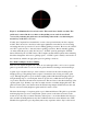
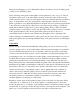
Figure 1. An illuminated red cross hair reticle. This reticle has a double cross hair. The guide star is centered in the cross hairs so that guiding errors can be detected and corrected by returning the guide star to its intended position in the cross hair using the motion keys on the drive corrector. Notably, the Compustar has a manual drive corrector incorporated directly into the computer module.
crosses the meridian, but this will not occur in the guide scope. Thus, even if the guide star is tracked perfectly in the guide scope, differential flexure between it and the imaging scope can result in a trailed image. Ironically, efforts to thwart this problem can be counterproductive. Attaching the guide scope to the imaging scope using rigid hardware may reduce the flexion, but it adds a significant weight load to the drive, making drive rate errors more likely.
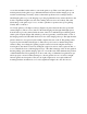
Figure 2A (left). An off-axis guider is a T-shaped connector that connects to the threads of the rear cell of the Compustar with the threaded ring at left. The threads to the right accept a T-ring for a camera or other adapter. The vertical “stem” of the T accepts an illuminated cross hair reticle eyepice with which the precise position of the guide star and guide errors can be judged.
not a problem with separate guide scopes in which the subject can always be framed as desired and a reasonably bright guide star can be selected quite far afield from that by adjusting the aim of the guide scope. Furthermore, acquiring the only suitable guide star may result in the off-axis guider being oriented at some very inconvenient angle for monitoring the guide star, like pointing down toward the ground (Figure 3).
during the actual imaging sessions. Planetarium software often has provisions for making such overlays for use with that program. Lastly, the image of the guide star through the off-axis guider may not be very good. The offaxis guider acquires stars, as the name implies, quite far off the optical axis of the telescope, where coma from an SCT‟s optics is more apparent. This gives comma shaped stars on which to guide.
Guiding Camera The guiding camera is not to be confused with the actual imaging camera at the prime focus of the telescope. Rather, it will be inserted where the guiding reticle eyepiece would have been placed. The guiding camera can be any one of a variety of imaging devices. It can be a small CCD designed specifically for autoguiding, as with the SBIG ST-4 autoguider.
Autoguiding Software Obviously, you can‟t just connect an imaging camera to a computer and expect it to begin interpreting the images and put out guiding correction commands that can be sent to the mount. That requires autoguiding software designed specifically for those tasks. In the case of the ST-4 and ST-V, proprietary autoguiding software was provided inside the electronics box. In other cases, the astrophotographer must obtain autoguiding software and load it into the computer.
Figure 5. Two examples of RJ-11 autoguiding cables, a flat ribbon cable on the left and a coiled cable on the right. An RJ-11 cable looks a just like a telephone cable, complete with modular telephone jacks, but it is not a telephone cable. RJ-11 cables will be discussed in detail below, but the important point to understand now is that the connector device must plug into the computer port you‟ve selected and also have a female RJ-11 modular jack plug, which looks like a female telephone jack plug.
Figure 6A (left). A GPINT connector, available from Shoestring Astronomy. Note the male plug to be connected to the parallel port on the autoguiding computer and the female RJ-11 modular jack port with copper connection pins, where the RJ-11 cable can be attached. Figure 6B (right). A GPUSB connector, available from Shoestring Astronomy.
Figure 7. The GPINT connector attached to the parallel port of the autoguiding computer and a coiled RJ-11 cable inserted into its female modular jack plug. Guide Port for the Telescope Mount Newer telescopes mounts have conspicuous guide ports where they receive computer input for autoguiding. They consist of another female RJ-11 modular jack plug that resembles a telephone modular jack port (Figure 8).
The Compustar Can Be Autoguided Fortunately, the answer is “Yes, the Compustar does have some other type of guide port”, and that almost seems like a miracle. It is another testament to the fact that the Compustar design was far ahead of its time. When Celestron began producing the Compustars, the concept of autoguiding barely existed. Other telescopes of that era had no provisions whatsoever for autoguiding. It was not at all clear in what direction the field of autoguiding might go.
Figure 9. The front edge of the Compustar computer module showing its three female DB-9 ports. Each port receives 9 pins. The right port is for an optional joystick, the left port is for output to a printer. The center DB-9 port is the guide port for autoguiding input. Figure 10. A computer cable with a male DB-9 connector plug. The connector is D-shaped and has 9 pins. We have to know which wires on the RJ-11 cable go to which pins on the DB-9 plug.
Many older telescopes, likes the Compustar, require electrical isolation between the electronics of the autoguiding computer and those of the telescope computer. Failure to do this can cause fatal damage to the telescope electronics. Being the Compustar computer module is not replaceable, we cannot afford to let this occur. The required electrical isolation will be provided in the form of electrical relay switches.
modular jacks on the opposite ends of the cable. There are two ways the modular jacks can be connected if the ribbon of cable is out laid out flat, (which can be a little difficult with a coiled cable, but one can keep track of which side is which from one end to the other.). One way is with the retaining clips on the same side of the cable, the other is with the retaining clips on opposite sides.
Figure 12. The color coding and pin numbering of an RJ-11 autoguiding modular cable jack. With the cable to the left and the copper wire pins of the modular jack to the right, the pins are numbered 1 through 6 from top to bottom and the order of colors of the wires connected to them is white, black, red, green, yellow, and blue, respectively. It is for this reason that the modular jacks on opposite ends of an RJ-11 cable must have the retaining clips on opposite sides.
receptacle for the retaining clip on the bottom, then pin 1 for the white wire will be on the left, and so on, with pin 6 for the blue wire on the right (Figure 13). Figure 13. View into a female RJ-11 modular jack port with the pins at the top and the receptacle for the retaining clip on the bottom, indicating how pin 1 for the white wire will be on the left. Pin 6 for the blue wire will be on the right.
In ST-4 language, the pin out for an RJ-11 cable (repeat, cable) is as follows: Pin # Wire Color Direction 1 White Not used 2 Black Ground/common 3 Red -X 4 Green -Y 5 Yellow +Y 6 Blue +X Thus, when the autoguiding computer issues guiding commands, they will pass through the selected USB port, parallel port, or serial port into the connector.
Figure 14A (left). The pin out of a female RJ-11 modular jack connector, such as one on a GPINT or GPUSB connector. The female plug will have pin 1 at the left and pin 6 on the right in systems using the ST-4 language. This will be the pin out on the connector coming out of the autoguiding computer. Figure 14B (right) The pin out and color coding of wires of an RJ-11 male jack and cable using ST-4 language.
Group (http://tech.groups.yahoo.com/group/CelestronCompustar-User/). Mr. Borgman published this in response to a request for autoguiding wiring posted on the Yahoo Compustar User‟s Group. He indicated that he had done this wiring for an observatory in Texas and would be happy to share the schematic. The diagram has two portions.
Figure 15. The modified wiring diagram for the relay interface between the RJ-11 cable from the autoguiding computer to the DB-9 connector for the guide port on the Compustar computer module, using the ST-4 language. The left side of the diagram shows wiring for an optional joystick to be connected to the joystick port on the right side of the Compustar computer module.
unless they are autoguiding directly from one of those devices instead of using an RJ-11 cable from an autoguiding computer. If the reader will be using one of those devices, then they may simply follow the indicated pin out for the wiring of the relay box. However, not having any experience with such cameras, the author advises readers attempting to autoguide with them to consult a competent electrical engineer before proceeding.
autoguider relay box would not operate unless pin 9 on the DB-9 connector plug was grounded. Subsequent tests by Tom Sorbel confirmed that pin 9 has to be grounded on any device plugged into the joystick and autoguide ports for it to be recognized as present by the Compustar computer module. However, in the joystick port on the right side, a grounded pin 9 is also a signal to the Compustar computer module to inactivate the 4 motion control buttons.
When the input stops, the electromagnetic field will decay, the spring will flip the relay switch back to its “nc” position and restore electrical balance on DB-9 pin 1 and movement in the X axis will not be in favor of either the +X or –X direction. Thus, extra movement in the +X direction will cease.
Figure 16. The assembled autoguider relay box. The coiled RJ-11 input cable with its modular jack at bottom center is not connected to the autoguiding computer in this illustration (see Figure 7 for illustration of that connection). The male DB-9 connector is plugged into the central port on the Compustar computer module. The computer module is not powered up in this illustration. Enabling The Autoguider Compustar users will be familiar with the usual speed settings on the Computer module.
There is a fourth speed, and that is “AUTO”. As the name implies, “AUTO” is for autoguiding. The computer module beeps four times when “AUTO” speed is selected. This selection switches control from the front right DB-9 port on the Computer module, where a joystick may be plugged in, to the middle DB-9 port, which is the autoguiding input port.
through the autoguiding software. Set the exposure time for the guiding camera so that the star is imaged well, but not saturated. Typical exposures would be 1-3 seconds. You may have to click on the guide star using the mouse to let the software know where your chosen guide star is on the chip. Some autoguiding programs automatically select the brightest star on the chip. Figure 17. An autoguider settings window.
relay box click as they flip from their “nc” to their “no” positions when the autoguiding computer commands the mount to move in any direction. You will also hear the relays click back to their “nc” positions when the commands have finished. These clicking sounds let you know the relay box circuits are working. The software then has all the information it needs to calculate how many pixels the mount moves per second in each direction along each axis.
guide camera chip and is lost. This takes some trial and error, but is best accomplished by placing the calibration star in the center of the guiding chip so it has the capability of moving as far as possible in both RA and Dec directions without leaving the chip. Within these constraints, the time interval selected should be about the same as the longest time required to manually correct the greatest periodic error that the RA drive makes.
framed on the imaging chip, just as you set it up before. With the software properly calibrated for that orientation of the guide camera, it will often be able to accurately autoguide on the fainter guide star, even though it was too faint for calibration. However, if the guide star and the calibration star are at significantly different declinations, you will have to compensate for this.
By the same token, if you set the autoguider aggressiveness to the maximum, you are likely to get rapid fire jerky movements of the mount as the guiding software tries to completely correct every detectable guiding error, no matter how small. This results in overcorrection and, ironically, poor tracking. Usually, an aggressiveness setting of 8 out of 10 gives the best results.
direction, then there may be some slack that has to be taken up whenever the next correction is in –Dec before the drive engages the gear teeth in the opposite direction. If guiding in Dec does not appear adequate, you may need to add backlash compensation. It may take some experimentation to find the correct setting. If the setting is too low, guiding corrections will be delayed while the backlash is being taken up. If the setting is too high, over correction will occur.
Fork mounted telescopes should be balanced first with the optical tube assembly aimed in the vertical direction, then in the horizontal direction. Begin by slewing the telescope so that it is centered on the meridian. Then, slew the telescope straight up at the zenith. While carefully keeping one hand on the telescope, so it doesn‟t swing out of control, slowly release the lock on the Dec axis and note which way the telescope wants to swing.
generate. All these problems result in guiding errors. The goal of rebalancing the telescope is to put the telescope‟s center of gravity back at that intersection, to restore optimal function of the system. By first balancing the telescope vertically, you ensure that the telescope‟s center of gravity lies somewhere along the longitudinal axis. If the telescope swings north, that means the center of gravity is actually somewhere above the longitudinal axis.
have counterweights in the left fork arm to counterbalance the declination drive box on the right fork arm. Most locations where equipment can be added to the Compustar are intentionally placed along the longitudinal axis of the telescope halfway between the right and left fork arms, like imaging equipment at the center of the rear cell, or the mounting brackets on the center top and bottom of the optical tube.
away from the Milky Way. Odds approach essentially 100% as one images subjects progressively closer to the Milky Way. Another wonderful feature about these cameras is that the much larger imaging chip can be used to calibrate the autoguiding software for making guiding corrections using the guide chip (many autoguiding software programs allow you to chose which chip to use during the calibration). This means that there is little fear of moving the calibration star completely off the chip.
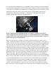
Figure 19A (left) The author’s SBIG STL 11000M CCD camera with the adapter plug (labeled RC-7) plugged into the camera’s autoguider output port. The female modular jack for an RJ-11 cable can be seen on the opposite end of the adapter, between the two metal set screws. Figure 19B (right). The SBIG STL 11000M CCD camera with the RJ-11 modular jack from the autoguider relay box plugged into the adapter on the CCD camera.
fatigued. The author has manually guided astrophotographs for long periods of time with no errors, only to make a single error pushing the wrong button just once, near the end of the exposure. This ruins the image by adding a small trailed blip to every bright star on the image. None of these issues are problems with autoguiding.
shot color) by taking many, many 30 second sub-exposures. This was because 30 seconds was the longest period that the Compustar could ever track an exposure without noticeable trailing. However, with the periodic error of the Compustar drive, only one-third of all exposures were actually useable; the other two-thirds had unacceptable trailing and had to be discarded. This was very inefficient.
Figure 21. M57, the Ring Nebula in Lyra. This is one of the author’s first autoguided images obtained with his Compustar 14 and the autoguider described in this article using a focal ratio of f/11. This image shows that despite the C14’s impressive focal length of 3900 mm, the Ring Nebula, measuring only 230 arcseconds, takes up only a small portion of the image. The image was acquired with an unmodified Canon 20D DSLR as the imaging camera, a Meade DSI as the guiding camera, and an off-axis guider.
Figure 22. M57, the Ring Nebula in Lyra, enlarged and cropped from the image in Figure 21. Note the fine structure detail in the upper right portion of the ring and the wisps of nebulosity visible inside the ring around the central star. The fact that the above image can bear this degree of enlargement and still show this amount of detail is amazing and is largely due to the sub-pixel accuracy of the autoguiding used to acquire the data.
Figure 23. The author’s “first light” image of M51, the Whirlpool galaxy and NGC 5195, obtained with the SBIG STL 11000M and the Compustar C14 and a 0.75x focal reducer (f/8). Admittedly, the galaxies are not centered because it was decided to use the brightest available guide star in the vicinity for this first attempt at autoguiding. Self-guiding has since been successful on much fainter stars, permitting better framing of subjects (see Figure 24).
Figure 24. M63, the Sunflower galaxy a self-guided image taken using the autoguider on the Celestron Compustar 14 with a 0.75x focal reducer (f/8). The image data were aquired on multiple nights from 2011-06-04 to 2011-06-20 using the author’s SBIG STL 11000M CCD camera with Baader Planetarium LRGB filters. About 20 faint background galaxies are visible in this image. Exposures: LRGB=152:48:48:52 minutes=5:00hours total exposure.
mass produced. It is estimated there are only 500 Compustar 14 telescopes, a number smaller than any other commercial model. Fortunately, this is not at all necessary. By building the autoguider relay assembly and connections described in this article, any Compustar can be autoguided and used to obtain beautiful long-exposure astrophotographs.