
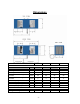
Product specifications


- 9 -
output from the system. Total duct work is recommended not to exceed 50’. If longer runs of
duct are required, secondary fans must be used to maintain CFM output.
o The condensate drain line needs to be considered when selecting an installation site.
o Unit should be level with the top side up during operation.
•
The unit is designed to operate with an ambient (air intake) temperature of 40 deg to 90 deg F.
•
All required parts are on-hand.
o The electrical plug and outlet have the correct configuration.
o Breakers are the proper size.
o The cellar has adequate insulation and vapor barrier.
o Ducts are the correct size.
o There is ample space around the unit to allow access for maintenance and repair.
Electrical Installation:
• The unit is designed so that it can be installed without opening the electrical access panel. If for any
reason the access panel needs to be opened it should be done only by qualified personnel.
• The unit main power (110VAC or 230VAC) branch circuit shall be fused at 15 to 20 amps.
• The unit has a delay timer that will not allow the compressor to start for a lock-out period after the power
has been disrupted. This time is adjustable but has been preset at the factory for 5 minutes.
• The unit is supplied with high and low pressure switches on the refrigerant line. These switches will not
allow the compressor to operate if the refrigerant charge is too low or too high. There is no manual
reset on either switch and normal operation should resume once the condition has been corrected.
Thermostat Connection:
• 24 VAC is on screw terminal 6 (red, R) of the screw
terminal block on the front panel.
• 24 VAC return or common is on screw terminal 5
(brown, B)
Note: The 24 VAC has circuit breaker protection.
• At a minimum the following control lines from the
thermostat are required:
o Cool (yellow, Y) on screw terminal 1
o Fan (green, G) on screw terminal 2
Notes:
• The unit has no internal support for humidity or heater
control. If a duct heater and or humidifier are co-
installed you may attach the thermostat humidifier
control line to screw terminal 3 (blue, B) and the duct
heater control line on screw terminal 4 (white, W).
• If a duct mounted heater and or humidifier are used
the humidifier must be downstream in the airflow
from the heater. Check local codes before installing
such equipment.