OWNERS MANUAL
We manufacture, test and certify 100% of our wine cooling units in the USA. By sourcing the best components and closely controlling our manufacturing processes, we can assure the highest-quality, lowest defect manufacturing rates in the industry. Copyright © 2011. CellarCool. All rights reserved. This manual, the product design, and the design concepts are copyrighted by CellarCool, with all rights reserved.
TABLE OF CONTENTS Quick Reference Guide Unit . . . . . . . . . . . . . . . . . . . . . . . . . . . . . . . . . . . . . . . . . . . . . . . . . . . . . 2 Controller. . . . . . . . . . . . . . . . . . . . . . . . . . . . . . . . . . . . . . . . . . . . . . . . 3 Fan Speed & Specifications. . . . . . . . . . . . . . . . . . . . . . . . . . . . . . . 4 Introduction. . . . . . . . . . . . . . . . . . . . . . . . . . . . . . . . . . . . . . . . . . . . . . . . 5 Receiving & Inspecting The Unit. . . . . . . . . .
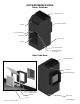
QUICK REFERENCE GUIDE Front / Side View Exhaust Collar Rear Intake Plenum Supply Air Sensing Probe Controller Power Inlet Return Fan Speed Control Condensate Pump Access Panel Rear / Side View Exhaust Plenum Drain Port Rear Intake Plenum Unattached Intake Plenum Register Power Inlet Filter Page 2 | 1-800-343-9463 UFM 070313
QUICK REFERENCE GUIDE Controller Layout Refer to page 24 for complete listing of buttons and symbols. Menu Navigation & Value Increase *Press and hold to manually enter anti-frost mode. Power On/Off (hold for approx. 3 seconds) & Escape Probe Values & Alarm Folder Menu Navigation & Value Decrease *Press and hold to enter the parameter menu.
FAN SPEED REFERENCE Your fan speed selection will depend on the amount of heat that needs to be removed from the cellar. Fan speed selection will depend on the cellar size, insulation factor, door seal and desired wine temperature. When initially installing the unit, set the fan speed to High setting for a quick chill down. Once the temperature of the cellar reaches the desired temperature, you may be able to select a lower fan speed to handle the normal load.
INTRODUCTION Customer Service Thank you for purchasing a CellarCool Ultimate FM Series cooling unit. We strive to provide the highest quality products and the best possible customer service. If you have any questions about your CellarCool unit, please call us at 1(800) 343-9463 or visit cellarcool.com. Using the Manual This User’s Manual is intended to assist in the proper installation and maintenance of the CellarCool cooling unit.
RECEIVING & INSPECTING THE UNIT Receiving and Inspecting the Unit • Lift only at the designated hand hold locations on the shipping container or fully support the unit from • • • • underneath. A shipment may include one or more boxes containing accessories. Before opening the container, inspect the packaging for any obvious signs of damage or mishandling. Write any discrepancy or visual damage on the Bill of Lading before signing.
QUICK START GUIDE This guide is meant to serve as a quick reference for installation of the CellarCool unit. The remainder of this Owner’s Manual will provide more detailed information and instructions. Upon receiving the CellarCool unit: 1. Inspect the unit before installation. If damage is found, please contact your distributor or CellarCool Customer Service at 1.800.343.9463 ext 799. 2. The unit should remain in an upright position for 24 hours prior to operation. 3.
PREPARING THE WINE CELLAR The performance and life of your CellarCool unit is contingent upon the steps you take in preparing the wine cellar. Note: Improperly preparing your enclosure or incorrectly installing your CellarCool unit may cause unit failure, leaking of condensation, and other negative side effects. IT IS HIGHLY RECOMMENDED THAT YOU OBTAIN THE ASSISTANCE OF A WINE STORAGE PROFESSIONAL.
Cooling Unit Keep Clear Unobstructed Airflow Unobstructed airflow to and from the unit is critical for the unit’s overall performance and life-span. A minimum three-foot clearance (five foot is ideal) area is crucial. The air the fans blow needs to circulate and either dissipate or absorb heat from the space, the more air to exchange the more efficient the unit will operate. Note: Avoid attempting to camouflage the unit. This will restrict airflow and thus the unit’s ability to work efficiently.
Ventilation The necessity of dissipating heat away from the unit is critical to the unit’s performance and cannot be overstated. As the unit operates and cools, a greater amount of heat is generated on the exhaust side of the unit. Adequate ventilation is required in order to dissipate heat away from the unit. If ventilation is inadequate, the exhaust will heat up the area or room and adversely affect the unit’s ability to cool.
PRE-INSTALLATION TEST THE UNIT PRIOR TO INSTALLATION To prepare it for testing before installation in wall: • Unit needs to be in the upright position for 24 hours before starting. • Remove unit from box • Plug in unit to electrical outlet • Turn on to test (see #4 on the Quick Start Guide for details). • Turn off after test Electrical Needs The CellarCool Ultimate FM Unit requires a dedicated 115-volt 20-amp circuit. The unit draws a large amount of amps at initial start up.
PREPARING THE INSTALLATION LOCATION Through-the-Wall Minimum Tools Needed Level Hammer Screwdriver Saw Locate the desired installation location. Using a stud finder, locate the studs on either side. Place the unit against the wall to determine the height of the Intake Plenum on the rear of the Cooling Unit. Using a level and a pencil, make an outline of a 12 1/4” square in between the two studs to provide an entry for the two Intake Plenums pieces. Using a saw, cut out the outlined square.
INSTALLING THE UNIT From outside the cellar: 1. Apply air-tight sealant or caulking on the area of the unattached Intake Plenum that will contact the wall (as shown in Figure 1).Make sure to seal all cracks and gaps. This will prevent heat transfer between the cellar and the adjacent area. 2. Slide in and secure the unattached Intake Plenum to the wall from out side of the cellar using sheetrock anchors or wood screws when going into a stud. FIGURE 1 FIGURE 2 From inside the cellar: 3.
INSTALLING THE UNIT From outside the cellar: Make sure to remove all insulation or debris left inside either Plenum prior to sliding the cooling unit against the cellar wall and connecting the Intake Plenum and the rear unattached Intake Plenum. 4. From outside the cellar seal all cracks and gaps where the two Intake Plenums meet on the inside of the unattached Intake Plenum with an air-tight sealant or caulking to prevent heat transfer between the cellar and the adjacent area (as shown in Figure 4). 5.
DRAIN LINE Condensation Drain Line Tube The condensation drain line tube is used to remove excess condensation from the unit to a proper discharge location. It is important that the drain line tube is properly connected and used to prevent leakage and other problems associated with excess condensation. Failure to use the condensation drain line tube will void the warranty on the unit.
DRAIN LINE PUMP SYSTEM CORRECT: Typical sequence of operation for correct Discharge Hose installation with Anti-Siphon Device 1. Drain pan fills with water which flows into reservoir. Intake hose between reservoir and pump is empty (filled with air). 2. Raising water lifts float, activating pump, which self primes by drawing water up from reservoir. During this period the pump is operating hot and dry and will click loudly.
DRAIN LINE PUMP SYSTEM INCORRECT: Failure to follow correct Discharge Hose installation will damage pump. 1. Drain pan fills with water which flows into reservoir. Intake hose between reservoir and pump is empty (filled with air). 2. Raising water lifts float, activating pump, which self primes by drawing water up from reservoir. During this period the pump is operating hot and dry and will click loudly.
INSTALLING THE DUCT WORK Building a Facade The Ultimate FM Cooling Unit is set up to have a variety of Ducting Installation Options. The exhaust may be ducted into the attic or out to the exterior of the house through the attic. The first option to consider is using a standard 6”x14” Duct Boot and 8” diameter duct work for the exhaust followed by building a facade around the duct work.
INSTALLING THE DUCT WORK Custom Duct Work Another Option that might be considered is building Insulated Custom Duct Work. Figure 6 below is an example that may be followed to create Insulated Custom Duct Work to extend to the attic using 1/2” Plywood, 1/2” Insulation Board and (24) Angle Brackets.
NOTES Page 20 | 1-800-343-9463 UFM 070313
DUCTING OVERVIEW Use of Ductwork Use ductwork to connect the Exhaust Collar on the top of the cooling unit to the desired exhaust area. Use only insulated ductwork to minimize cooling losses and reduce noise. Note: Do not exceed a total of 15’ for the length of ductwork. Avoid crimping the flexible ducts. This chokes down the inside area and reduces the airflow causing the unit to operate improperly. Be sure all duct work is insulated.
MULTI SPEED FAN CONTROL Designed for wine cellars up to 2000 cubic feet, the Ultimate FM 8000 features multi-speed fans with a “high” setting for maximum performance in high-temperature (+110°F) environments and a “low” setting for superquiet operation. Fan Speed Selector Switch (Low/High): The cooling unit fans may operate on two speed settings: Low and High. For optimum sound and energy efficiency, select the lowest fan speed that will maintain the desired cellar temperature.
UNIT OPERATION Initial Start-Up: When power is applied to the unit, the control will briefly display all symbols, and the Compressor symbol will be displayed (if unit is calling for cooling). There may be a brief delay prior to the evaporator and condenser fans turning on. Set Point: The set point is set from the factory (Cellarcool) at 55°. It can be adjusted by the customer between 50° and 70° in one degree increments.
CONTROLLER FUNCTIONS Button/Symbol Normal Functions ON/OFF • • Up and Down • • SET • • • • • Press and hold the on/off button for approximately 3 seconds to turn the unit on or off. Note: This does not disconnect power from the unit. In order for the power to be shut off from the unit, the power cord must be unplugged from the wall receptacle. This button also serves as an escape button. Use these buttons to scroll up or down a menu.
Alarm Codes Message “E1” “E2” Cause Solution Faulty Air Sensing Probe Connection 1. Check Air Sensing Probe attachment at circular connector. 2. Check Air Sensing Probe connection at the back of controller. Defective Air Sensing Probe Replace the Air Sensing Probe. Faulty Evaporator Probe Connection Check Evaporator Probe connection at the back of controller. Defective Evaporator Probe Replace the Evaporator Probe. “AH1” The Air Sensing probe is 1.
Blue Black Gray Purple Red Condensate Pump 3 NC 7 4 C 8 2 NO 6 Blue White Blue Blue Green Green Green Gray Evap. Fan Gray d Re Capacitor Red White Brown t Compressor al utr Ne Cond. Fan nd ou Gr Ho 1 COMP 0 Crankcase Heater 8 9 10 11 Black Black Orange Green Eliwell 974 White 1 2 3 4 5 6 7 (+) Black Green White Black Black Brown White 2 Way F.S.
MAINTENANCE SCHEDULE Monthly 1. Check Coils 2. Check for unusual noise or vibration 3. Check the drain line to see if it is above the waterline if draining into a vessel. Quarterly 1. Clean Coils 2. Replace Filters on the duct work. 3. Check the drain line pump and thoroughly clean the reservoir, filter and float with an antibacterial cleansing solution. 4. All drain line hoses should be checked for leaks. Annually 1. Replace filters if worn or plugged beyond cleaning. 2.
TROUBLESHOOTING GUIDE Unit has ice forming on the Evaporator Possible Cause Solution Evaporator coil is dirty. Clean coil with a vacuum. If coil is very dirty, use a small hand spray with a small amount of liquid dish washer detergent. Spray coil, let set for 5 min, then flush with fresh water. There is something blocking the supply and or return air Remove blockage The evaporator fan is not turning on. Call a service tech to troubleshoot The Unit has not gone through its anti-frost sequence, yet.
TROUBLESHOOTING GUIDE Unit leaks water Possible Cause Solution Unit is not level Unit should be level to prevent leaking. Drain line clogged or kinked Check drain line to make sure water can flow freely. Drain is clogged preventing water form escaping Disconnect drain and clear out, open access door and check drain for blockage Coil is iced causing drain pan ice and water overflowing Melt ice with blow drier.
TROUBLESHOOTING GUIDE Pump runs all the time Possible Cause Solution Float is positioned with the magnet facing downwards. Reposition the float with the magnet facing up wards. The float is not in the correct location. Check that the float is located inside the reservoir around the sensor column. The top is not secured properly to the reservoir. Make sure that the top is clipped firmly on to the reservoir. Sludge has built up and is preventing the float to rest on the bottom of the reservoir.
TECHNICAL ASSISTANCE & ACCESSORIES CellarCool Customer Service is available Monday through Friday from 8:00 a.m. to 4:00 p.m. Pacific Time. The customer service representative will be able to assist you with your questions and warranty information more effectively if you provide them with the following: • The model and serial number of your CellarCool Series Unit. • Location of unit and installation details, such as ventilation, ducting, construction of your wine cellar, and room size.
Ultimate Series Product Warranty Information CellarCool Product Terms and Conditions Including Product Limited Warranty And Product Installation Requirements For CellarCool Extreme Series ATTENTION: PLEASE READ THESE TERMS OF USE CAREFULLY BEFORE INSTALLING YOUR CELLARCOOL COOLING SYSTEM. INSTALLING YOUR CELLARCOOL COOLING SYSTEM INDICATES THAT YOU ACCEPT AND AGREE TO EACH OF THE TERMS AND CONDITIONS SET FORTH HEREIN (“TERMS OF USE”).
1. warranty. 2. Proof of purchase of the Product in the form of a bill of sale, receipted invoice or serial number, which is evidence that the Product is within the Limited Warranty Period, must be presented by the End User to CellarCool in order to obtain limited warranty service. 3. This limited warranty is void if the factory applied serial number has been altered or removed from the Product. 4.
function properly. Periodically cleaning the Product’s vents will help assure maximum cooling efficiency. The drain tube must also be checked and kept clean and free of debris and mold to maintain proper performance. Mold is a natural living organism in the environment. It exists in the air in the form of microscopic spores that move in and out of buildings through doors, windows, vents, HVAC systems and anywhere else that air enters. Once it is discovered, mold must be addressed quickly and appropriately.
No waiver by CellarCool of any breach or default of the contract of sale (including these Terms and Conditions of Sale) concerning a Product will be deemed to be a waiver of any preceding or subsequent breach or default. E. Correction of Errors and Inaccuracies. These Terms and Conditions may contain typographical errors or other errors or inaccuracies.
CellarCool 1738 E. Alpine Ave Stockton, CA 95205 1(855) 235-5271 www.cellarcool.