
Owner`s manual

19
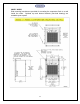
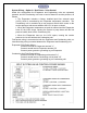
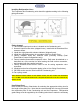
Installing Refrigeration Lines
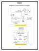
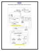
The Evaporator and Condensing units should be piped according to the following
piping schematic:
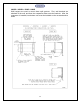
Piping Legend
1. The 3/8"ODS liquid service valve is located on the Condensing unit.
2. Hermetic liquid line filter drier (shipped loose). Install with the directional flow
arrow as shown.
3. Liquid line sight glass with moisture indicator (shipped loose).
4. Liquid line refrigeration piping in accordance with Line Sizing Chart.
5. Factory installed liquid line solenoid valve (normally closed) (Dual
Power/Valve Control configurations only).
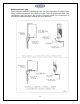
6. Factory installed thermostatic expansion valve. Bulb must be attached to a
horizontal run of the suction line after brazing the field suction connection,
and insulated with the supplied cork tape.
7. Factory installed suction service valve to use for setting expansion valve
superheat.
8. Insulated suction line refrigeration piping (refer to Line Sizing Chart below).
9. 5/8"ODS suction service valve located on Condensing unit.
10. Fan cycling control
WHEN BRAZING COPPER TUBING TO THE SERVICE VALVES, USE 95/5 SOLDER AND SOLDERING
FLUX.DONOTUSESILVERSOLDERBECAUSEITREQUIRESHIGHERHEATTHATWILLDAMAGETHE
SERVICEVALVES.
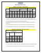
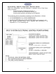
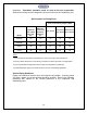
Line Sizing Chart
Refer to the Line Sizing Chart below for selecting the appropriate tubing size for
the length of the piping run. Note that the recommended line size may not match
the connection ports on the Condensing unit and the Evaporator. Refrigeration
grade fittings must be supplied by the installing technician to make the necessary