Force5-50 2G-3G-4G 5-Band Wireless Adjustable Cellular Booster Kit Introduction Theory of Operation Packages Contents Booster Hardware Introduction Theory of Operation Installation Quick Install Guide Configuring Gain Setting Installation Steps Troubleshooting Safety Information User Guide
INTRODUCTION Thank you for your purchase of the Force5-50. The Force5-50 5-Band adjustable cellular signal booster removes the frustration over dropped calls, limited range and slow data rates by amplifying incoming and outgoing cellular signals in large watercraft. The Force5-50 enhances 2G, 3G and 4G data reception data for all major US. Carriers. This guide contains all the information you’ll need to get your Force5-50 booster system up and running.
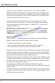
INTRODUCTION Package Contents: Unpack all package contents, compare them against the package contents list, and check for damage. For missing or damaged items, contact your retailer. Keep the carton and packing material to store the product or if you need to return it.
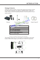
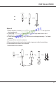
INSTALLATION Quick Install Guide Installation The Force5-50 booster kit is specially designed for marine applications. It can also be used for other applications with the right antennas, cables and mounting hardware. Step 1. Connect the SC-200 Outside Antenna The SC-200 is a, full-band antenna, ideal for marine use. Option 1 (Recommended) 1. Choose a mounting location that is as high as possible, free from obstructions and as far as possible from other antennas and sources of RF signal. 2.
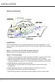
INSTALLATION N connector 2 1 2 1 1 Option 2 1. When location of outside antenna has been determined, remove cap from ferrule side hole. 2. Feed FME connector (small end) and cable through side hole on the f shown in the figure below. 3. Feed remainder of cable through ferrule hole until approximately 1” of cable remains. 4. Connect N connector to antenna. 5. Screw antenna onto ferrule, bend cable to prevent cable from twisting. 6. Screw base onto other end of ferrule. 7. Mount base onto location.
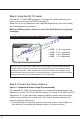
Step 2. Using the SC-174 cable Use the SC-174 cable FME connector to connect the outside antenna to the boost connector marked OUTSIDE (see page 3). Make sure to not coil additional coax cable that might be left over from installation. Hand tighten the connection. Before installing Indoor Antenna check the table below for optimum coverage. Adjust dB Gain according to table below if you cannot achieve maximum separation.
2. Using supplied plate, mark position of desired placement with a pencil or marker. 3. Screw (not supplied) mounting plate into place with the slide panel protruding towards you. Provided plastic anchors are only to be used for sheetrock installation. 4. Slide antenna securely onto mounting plate. 5. Use the additional SC-174 cable to connect the antenna to the booster connector labeled (INSIDE). Note: Be sure to provide enough separation from outside antenna (see table on page 6.
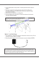
Step 4. Install the Signal Booster 1. Select a location close to a working AC outlet. Do not expose the signal booster to excessive heat, direct sunlight, moisture, and airtight enclosures. 2. If you’d like to mount the booster to a wall, mark location of screw tabs on the wall in the desired location 3. Use supplied screws or appropriate screws for surface of mounting location and drill through screw tab holes on booster. 4.
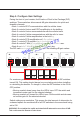
Step 5. Configure Gain Settings Facing the front of your booster, find 9 banks of Dual In-line Package (DIP) switches. These switches allow manual dB gain attenuation for uplink and downlink channels. •B ank 1 controls AT&T communications with the cellular tower. • Bank 2 controls Verizon and AT&T amplification in the building. • Bank 3 controls Verizon communications with the cellular tower •B ank 4 controls Cellular communications with the cellular tower.
To Achieve... Set the DIP Switchs in the Same Bank as Follows... SW1 (1 dB) SW2 (2 dB) SW3 (4 dB) SW4 (8 dB) SW5 (16 dB) 0 DB OFF OFF OFF OFF OFF 1 DB ON OFF OFF OFF OFF 3 DB ON ON OFF OFF OFF 7 DB ON ON ON OFF OFF 15 DB ON ON ON ON OFF 21 DB ON OFF ON OFF ON 31 DB ON ON ON ON ON Note: As you see from the table above, attaining the recommended indoor and outdoor antenna separation optimizes coverage significantly.
LED Designation 5 AWS 2100 Uplink 6 Power Description OFF = normal operation. ON = AWS uplink warning. Power off booster immediately. Green ON or blink = booster receiving power. OFF = booster not receiving power Red ON = oscillation has occurred for longer than 15 minutes and the booster is shutting down Automatic Shutdown SureCall boosters that have automatic shutdown work in the following way: 1. The cellular side (LEDs 4 and 5) is usually the first side to experience oscillation.
Problem Resolution Signal booster has no power Verify that the booster switch is turned on. Connect the power supply to an alternate power source. Be sure the AC outlet is working and is not controlled by a wall switch that can cut power to the outlet. If the green POWER LED on the signal booster is OFF, return the power supply to SureCall. Contact tech support at 1-888- 365-6283 or support@surecall.com, or go to www.surecall.
Problem Resolution The Alert LEDs flash after the initial activation period. Lower the dial above the blinking LED by 5dB (for example, from 65 to 60) and monitor the bars on your cell phone to see whether reception has improved. The Alert LEDs continue to flash The singal booster shuts down automatically, and then restarts after 60 seconds. Turn down the Cellular, PCS or LTE/AWS dial that is oscillating dial that is to prevent the signal booster from shutting down autimatically.
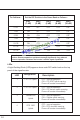
Vehicle Kitting Component Gain/Loss Product Number/ Description LTE-A LTE-V 800 MHz 1900 MHz Outdoor Antenna* SC-200 3dBi 3dBi Outdoor Cable SC-174 3.8dB 3.8dB Indoor Antenna SC-110W (table top) 1.1dBi 1.1dBi Indoor Cable SC-174 3.8dB 3.8dB 4.3dB 3dBi 1700 MHz/2100 MHz 5dBi 5dBi/5dBi 4.3dB 8.8dB 6.98dB/8.96dB 1.1dBi 3dBi 3dBi/3dBi 8.8dB 6.98dBi/8.
Three-Year Product Warranty SureCall warrants its products for three years from the date of purchase against defects in workmanship and/ or materials. Specifications are subject to change. The three-year warranty only applies to products meeting the latest FCC Certification Guidelines stated on 2/20/2013 and going into effect April 30, 2014. A two-year warranty applies to any products manufactured before May 1, 2014.
Limitations of Warranty, Damages and Liability: EXCEPT AS EXPRESSLY SET FORTH HEREIN, THERE ARE NO WARRANTIES, CONDITIONS, GUARANTEES, OR REPRESENTATIONS AS TO MERCHANTABILITY, FITNESS FOR A PARTICULAR PURPOSE, OR OTHER WARRANTIES, CONDITIONS, GUARANTEES, OR REPRESENTATIONS, WHETHER EXPRESSED OR IMPLIED, IN LAW OR IN FACT, ORAL OR IN WRITING. SURECALL AGGREGATE LIABILITY IN DAMAGES OR OTHERWISE SHALL NOT EXCEED THE PAYMENT, IF ANY, RECEIVED BY CELLPHONE-MATE, INC.
Note: This equipment has been tested and found to comply with the limits for a Class B digital device, pursuant to part 15 of the FCC Rules. These limits are designed to provide reasonable protection against harmful interference in a residential installation. This equipment generates, uses and can radiate radio frequency energy and, if not installed and used in accordance with the instructions, may cause harmful interference to radio communications.