
Install guide
10
15 DB
21 DB
31 DB
ON
ON
ON
ON
ON
ON
ON
OFF
ON
ON
OFF
ON
OFF
ON
ON
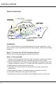
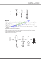
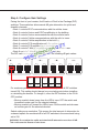
To Achieve...
Set the DIP Switchs in the Same Bank as Follows...
SW1
(1 dB)
0 DB
1 DB
OFF
ON
OFF
OFF
OFF
OFF
OFF
OFF
OFF
OFF
SW2
(2 dB)
SW3
(4 dB)
SW4
(8 dB)
SW5
(16 dB)
3 DB ON OFFON OFF OFF
7 DB ON ONON OFF OFF
Note: As you see from the table above, attaining the recommended indoor and
outdoor antenna separation optimizes coverage signicantly. Any reduced
antenna separation deceases the booster’s cellular signal capabilities.
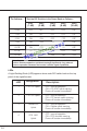
LEDs
A Light-Emitting Diode (LED) appears above each DIP switch bank on the top
panel of the signal booster.
LED
1
2
3
LTE 707 Uplink
LTE 781 Uplink
Cellular 800
Uplink
OFF = normal operation.
ON = LTE AT&T uplink warning.
Power o booster immediately.
OFF = normal operation.
ON = LTE Verizon uplink warning.
Power o booster immediately.
OFF = normal operation.
ON = Cellular uplink warning.
Power o booster immediately.
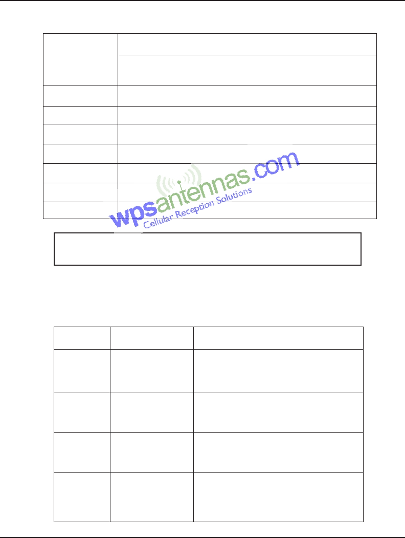
Designation
Description
4 PCS 1900
Uplink
OFF = normal operation.
ON = PCS downlink warning.
Power o booster immediately.