
Owner's manual

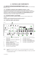

A
B
Spring
DC
WD
Cone
I 0184 - 5
GB
3 - START-UP
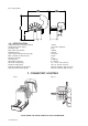
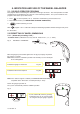
3.1 - ANCHORING
The machine can operate on any fl at non resilient fl oor.
Make sure that the machine rests solely on the three support points provided (fi g.2a).
It is advisable to secure the system to the ground using the specifi c feet (see fi g. 2a) in the event
of continual use with wheels weighing over 35 Kg.
3.2 - ELECTRICAL CONNECTION
The machine is supplied with a single phase mains cable plus earth (ground).
The supply voltage (and mains frequency) is given on the machine nameplate. It cannot be changed.
Connection to the mains should always be made by expert personnel.
The machine should not be started up without proper earthing.
Connection to the mains should be through a slow acting safety switch rated at 4 A (230V) or 10 A (115V).
See enclosed wiring diagram.
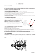
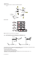
3.3 - ADAPTER MOUNTING
The wheel balancer is supplied complete with cone type
adapter for fastening wheels with central bore. Other optional
adapters can be mounted:
a) Remove threaded end piece A after backing off screw B.
b) Mount the new adapter (see enclosed brochures).
NOTE: CAREFULLY CLEAN THE COUPLING SURFACES
BEFORE PERFORMING ANY OPERATION.
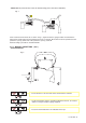
3.4 - FITTING AND ADJUSTING THE GUARD
a) Insert the wheel guard tube in its seat.
b) Fit the mounting bolts and tighten them securely.
The guard closed position can be adjusted by means of relative screw accessible from the rear of the
machine. Adjust the angular position of microswitch control.
Correct position is the one which keeps the tube exactly horizontal with the wheel guard closed (for
the standard guard (fi g. 1). For the 42” guard, see guard and dimensions in fi g. 1A.
3.5 - SPACER WD
When balancing very wide wheels (9”), there is not enough space to turn the distance gauge. To withdraw
the wheel from the machine side, fi t spacer WD on the adapter body and secure it with the standard issue
nuts. When centring the wheel with the cone on the inside, fi t the DC spacer to obtain spring thrust.
Fig.3a
Fig. 3