
Owner's manual


I 0184 - 6
GB
4 - CONTROLS AND COMPONENTS
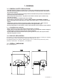
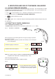
4.1 - MANUAL DISTANCE MEASUREMENT GAUGE ( C 61 )
This gauge serves for manual measurement of the distance of the point of application of the counterweight
FI from the machine.
4.2 - AUTOMATIC DISTANCE AND DIAMETER GAUGE ( C 61Z )
This gauge allow measuring distance of the rim from the machine and the diameter at the point of
application of the counterweight. The same gauge can be used to position correctly the counterweights
inside the rim, using the specifi c function (see EXACT CORRECTION POSITION INDICATION ), that enables
display of the position used for measurement (for calibration, see AUTOMATIC PRESETTING ( C61 Z ) ).
The gauge may only be used with the weight-holder pincer fi tted.
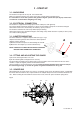
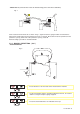
4.3 - AUTOMATIC WHEEL POSITIONING
At the end of the run, the wheel is positioned in relation to external or static out-of-balance (when
selected).
Positioning is disabled automatically for wheels less than 13” in diameter.
Accuracy is approx. ± 20 degrees for wheels weighing up to 25 Kg.
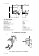
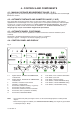
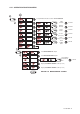
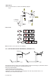
4.4 - CONTROL PANEL AND DISPLAY
Fig. 4
1-2 Digital readouts, AMOUNT OF UNBALANCE,
inside/outside
3-4 Digital readouts, POSITION OF UNBALANCE,
inside/outside
5 Indicators, correction mode selected
6 Indicators, selection made
7 Push button, unbalance reading < 5 g (25 oz)
8 Push button, operator selection
9 Push button, selection of mode of correction
10 Push button, SPLIT (unbalance resolution)
11 Push button, FUNCTIONS MENU
12 Push button, menu selection confi rmation
13 Push button, cycle start
14 Push button, emergency/home
15 Push buttons, manual DISTANCE setting
16 Push buttons, manual DIAMETER setting
17 Push buttons, manual WIDTH setting
Note: - Press buttons only with your fi ngers. Never use the counterweight pincers or other pointed
objects.
- When the beep signal is enabled (see OPERATION FUNCTIONS MENU) pressing of any push button
is accompanied by a “Beep”.